Method for controlling an artificial orthotic or prosthetic knee joint

A knee joint and artificial technology, applied in artificial legs, prostheses, medical science, etc., can solve the problems of component consumption and long development time

Active Publication Date: 2014-12-24
OTTO BOCK HEALTHCARE IP GMBH & CO KG
View PDF5 Cites 12 Cited by
  • Summary
  • Abstract
  • Description
  • Claims
  • Application Information

AI Technical Summary

Problems solved by technology

Disadvantages of this are long development times and the use of complex components

Method used


Image

  • Method for controlling an artificial orthotic or prosthetic knee joint
  • Method for controlling an artificial orthotic or prosthetic knee joint
  • Method for controlling an artificial orthotic or prosthetic knee joint

Examples


Embodiment Construction

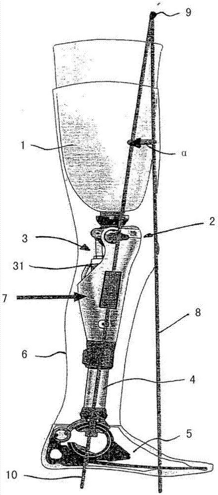
[0019] exist figure 1 In the diagram, a prosthetic leg is provided which has a prosthetic shaft 1 for receiving the thigh stump and for fastening the prosthetic leg to the patient. Arranged at the distal end of the prosthetic shaft 1 is a prosthetic knee joint 2 which is equipped with a resistance device 3 , for example in the form of a hydraulic damper or a wrap-around spring brake. A calf tube 4 and a prosthetic foot 5 are provided at the distal end of the prosthetic knee joint 2 as further distal components. The functional element consisting of the prosthetic shaft 1 , the prosthetic knee joint 2 , the calf tube 4 and the prosthetic foot 5 is wrapped by the decoration 6 in order to give the overall impression as natural as possible.

[0020] In the exemplary embodiment shown, an inertial sensor 7 is provided as an angle sensor on the lower leg component consisting of the distal part of the prosthetic knee joint 2 , the lower leg tube 4 and the prosthetic foot 5 . Inertial...


PUM


Abstract

The invention relates to a method for controlling an artificial orthotic or prosthetic knee joint (2), on which a lower leg component (4, 5) is arranged and which is assigned a resistance device (3) having at least one actuator (31), by means of which the bending resistance is modified depending on sensor data that is determined during use of the orthotic or prosthetic knee joint by means of a sensor (7), wherein the absolute angle of the lower leg component (4, 5) is determined exclusively by means of at least one inertial sensor (7), the angle determined is compared with at least one threshold value, and the bending resistance is modified when the threshold value is reached.

Description

technical field [0001] The invention relates to a method for controlling an artificial orthotic or prosthetic knee joint on which a lower leg component is arranged and which is equipped with a resistance with at least one actuator A device by which the bending resistance is varied by means of the actuator as a function of sensor data which is ascertained by at least one sensor during use of the orthotic or prosthetic knee joint. Background technique [0002] Prosthetics - or corrective knee joints that replace or support the function of the normal knee joint. In order to achieve the best possible functionality of the artificial knee joint, there are various designs on the market which influence the behavior of the knee joint during the stance and swing phases. Electromechanical knee joints are known in which the movement is detected by means of a plurality of different sensors and based on the sensor data a resistance device is controlled by which the bending resistance or ...

Claims


Application Information

Patent Timeline
Patent Type & Authority Applications(China)
IPC IPC(8): A61F2/64A61F2/68A61F5/01
CPCA61F2/64A61F5/0123A61F2002/6818A61F2002/7625A61F2002/764A61F2/68A61F2/72
Inventor E·拉奇
Owner OTTO BOCK HEALTHCARE IP GMBH & CO KG
Why Eureka
Try Eureka