A rapid cooling pressure cooking device

A cooking device and rapid cooling technology, applied to pressure cookers, cooking utensils, household appliances, etc., can solve the problems of increasing product power consumption, complex air-cooling structure, and increasing the cost of accessories

Active Publication Date: 2016-06-08
JOYOUNG CO LTD
View PDF7 Cites 0 Cited by
  • Summary
  • Abstract
  • Description
  • Claims
  • Application Information

AI Technical Summary

Problems solved by technology

[0002] At present, pressure cooking appliances such as electric pressure cooker and pressure cooker have many advantages such as fast cooking, high cooking temperature, and good food taste, which have become indispensable cooking appliances in our kitchen. But the problem that plagues the entire industry now is that although the electric pressure cooker cooks the food quickly, because of the high pressure in the pot, the lid of the pot cannot be opened in time, which brings great inconvenience to users.
[0003] In order to solve the above problems, there are two schemes of air cooling and water cooling. polluted
The water-cooling scheme is mainly driven by a water pump to cool the cooling water, which increases the cost of accessories, and the structure is complicated, which increases the power consumption of the product, which is not conducive to the promotion and popularization of the product

Method used


Image

  • A rapid cooling pressure cooking device
  • A rapid cooling pressure cooking device
  • A rapid cooling pressure cooking device

Examples


Embodiment approach

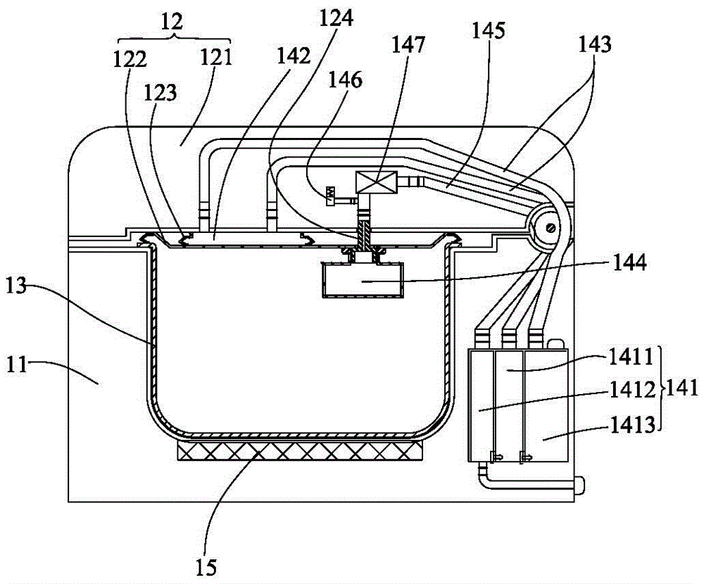
[0032] see figure 1 As shown, the first embodiment of a rapid cooling pressure cooking device of the present invention includes a pot body 11, a pot cover 12, an inner container 13, a cooling device and a heating device 15 located at the bottom of the pot body, and the inner container 13 is placed on the pot body In 11, pot cover 12 comprises outer cover 121 and inner cover 122, and pot cover 12 fastens airtight liner 13, and cooling device comprises the water tank 141 that cooling water is housed, cooling chamber 142, the circulating water pipe 143 that communicates water tank and cooling chamber. The cooling device also includes a steam pressure chamber 144, the steam pressure chamber 144 is installed on the inner cover 122, the steam pressure chamber 144 is provided with an exhaust pipe 145 communicating with the water tank 141, the heating device 15 heats the inner container 13, and the inner container 13 The high-temperature steam heats the steam pressure chamber 144, and...

Embodiment approach 2

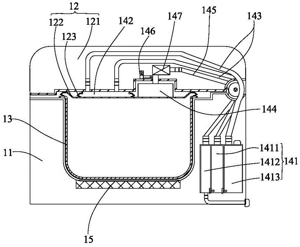
[0046] see image 3 As shown, the second embodiment of a rapid cooling pressure cooking device of the present invention differs from the first embodiment in that: the steam pressure chamber 144 and the cooling chamber 142 are installed on the same side of the inner cover 122 facing away from the inner container 13 on the side. In this way, the surface of the inner cover 122 facing the inside of the inner 13 is relatively flat, and the user can directly scrub the inner cover.

[0047] Certainly, the side of the inner cover 122 facing away from the liner can also be provided with a concave cavity, and the steam pressure chamber 144 is installed in the concave cavity.

[0048] The remaining structures and beneficial effects of this embodiment are consistent with those of the first embodiment, and will not be repeated here.

Embodiment approach 3

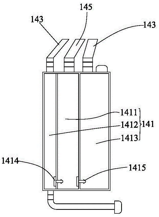
[0050] see Figure 4 As shown, the third embodiment of the rapid cooling pressure cooking device of the present invention differs from the first embodiment in that: the water tank 141 includes a sealed air intake water chamber 1411 connected to the steam pressure chamber 144 through the exhaust pipe 145 1. Return water cavity 1412, the bottom of the intake water cavity 1411 is connected to the cooling cavity 142 through the circulating water pipe 31, the top of the return water cavity 1412 is connected to the cooling cavity 142 through the circulating water pipe 31, and the return water cavity 1412 is provided with a single valve facing the intake water cavity to valve 32.

[0051] Further, a one-way valve is provided at the bottom of the inlet water chamber 1411 where it is connected to the circulating water pipe 31 to avoid water backflow.

[0052] In this embodiment, compared with the first embodiment, the circulating water pipe 31 directly replaces the water outlet cavity...


PUM

PropertyMeasurementUnit
Volumeaaaaaaaaaa

Abstract

The invention relates to a rapid cooling pressure cooking device, which comprises a pot body, a pot cover, an inner container, a cooling device and a heating device located at the bottom of the pot body, the inner container is placed in the pot body, the pot cover includes an outer cover and an inner cover, and the pot The lid is fastened to seal the inner tank, and the cooling device includes a water tank filled with cooling water, a cooling cavity, and a circulating water pipe connecting the water tank and the cooling cavity. The cooling device also includes a steam pressure chamber, the steam pressure chamber is installed on the inner cover, the steam pressure chamber is provided with an exhaust pipe connected to the water tank, the heating device heats the inner tank, the high temperature steam in the inner tank heats the steam pressure chamber, and the steam pressure The water in the chamber is heated to form pressure steam, and the pressure steam enters the water tank through the exhaust pipe, and the cooling water in the water tank is under pressure and enters the cooling chamber through the circulating water pipe to circulate and cool the steam in the inner tank. The steam in the inner tank is directly used to heat the steam pressure chamber to form the power to drive the water in the water tank, which not only saves the cost of the water pump, but also reduces the driving power of the water pump.

Description

【Technical field】 [0001] The invention relates to the field of kitchen appliances, in particular to a rapidly cooling pressure cooking device. 【Background technique】 [0002] At present, electric pressure cookers, pressure cookers and other pressure cooking appliances have many advantages such as fast cooking, high cooking temperature, and good food taste, which have become indispensable cooking appliances in our kitchens. Cooking is completed, but because of the high pressure in the pot, the pot cover cannot be opened in time, which brings great inconvenience to the user. [0003] In order to solve the above problems, there are two schemes of air cooling and water cooling. The air cooling structure is complicated and because there is a lot of oily fume in the kitchen, the long-term air duct circulation causes the interior to be easily polluted. The water-cooling scheme is mainly driven by a water pump to cool the cooling water, which increases the cost of accessories, and ...

Claims


Application Information

Patent Timeline
IPC IPC(8): A47J27/08A47J27/092
Inventor 朱泽春杜淑龙杨臣
Owner JOYOUNG CO LTD
Why Eureka
Try Eureka