Brittle material base board parting tool and brittle material base board supporting fixture

A technology of brittle material substrates and support clips, which is applied in the direction of manufacturing tools, stone processing equipment, fine working devices, etc., can solve the problems of large and expensive devices, unsuitable for cutting, etc., and achieve the effect of preventing damage and suppressing protruding corners

Inactive Publication Date: 2014-12-31
MITSUBOSHI DIAMOND IND CO LTD
View PDF17 Cites 2 Cited by
  • Summary
  • Abstract
  • Description
  • Claims
  • Application Information

AI Technical Summary

Problems solved by technology

Therefore, a frame for lifting and lowering the cutting rod, a driving source for lifting and lowering, and a suction mechanism or a pressing member for stably holding the substrate on the table are required, which increases the size of the device and becomes expensive.
In addition, it is necessary to perform various initial settings of the operating parts such as the positioning of the substrate on the table, the feeding pitch, and the pressing pressure of the cutting lever when the device is first operated, and it is not suitable for cutting a small number of substrates (that is, it is not a standard for mass production). substrates other than products, etc.)

Method used


Image

  • Brittle material base board parting tool and brittle material base board supporting fixture
  • Brittle material base board parting tool and brittle material base board supporting fixture
  • Brittle material base board parting tool and brittle material base board supporting fixture

Examples


Embodiment Construction

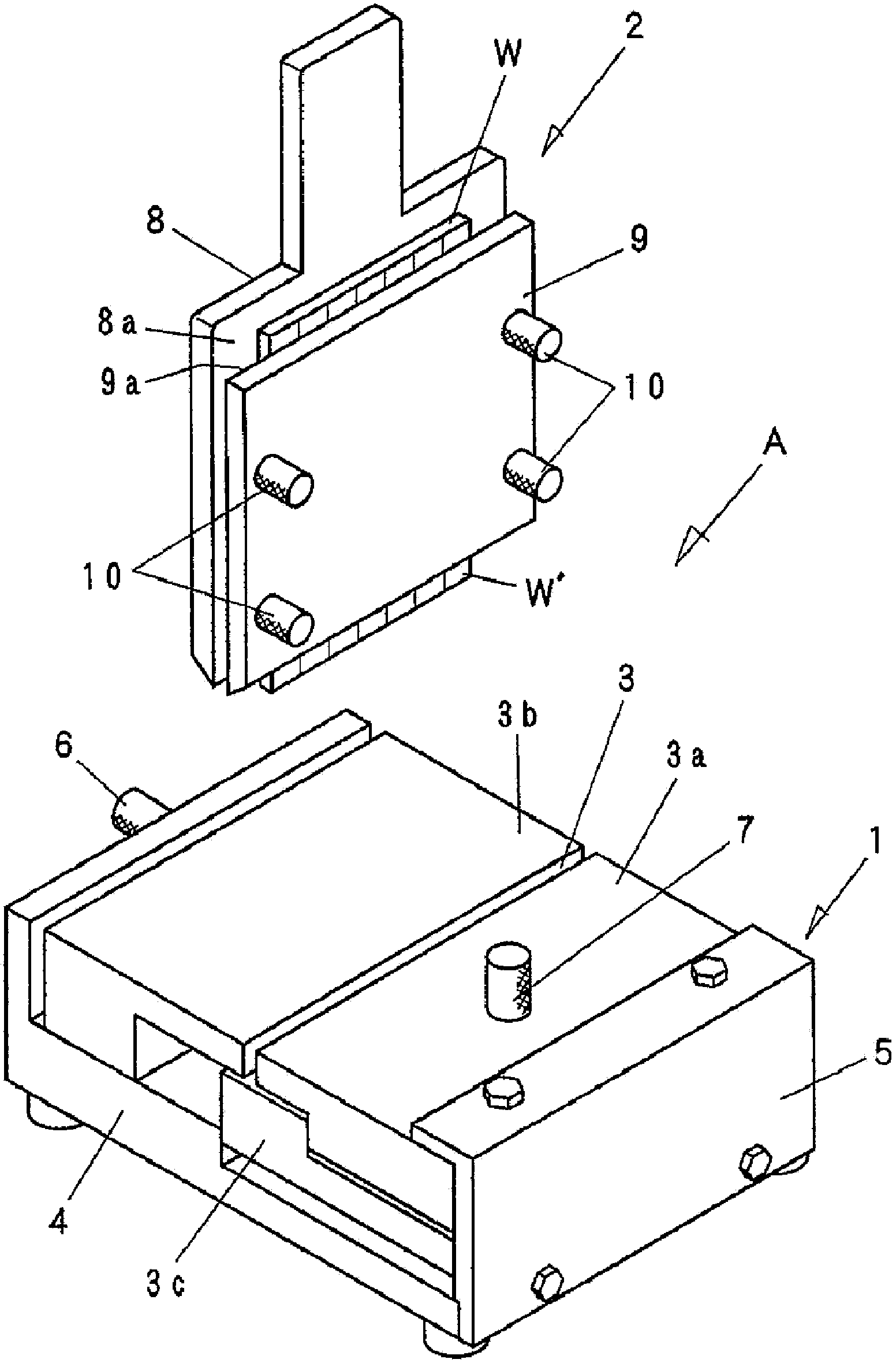
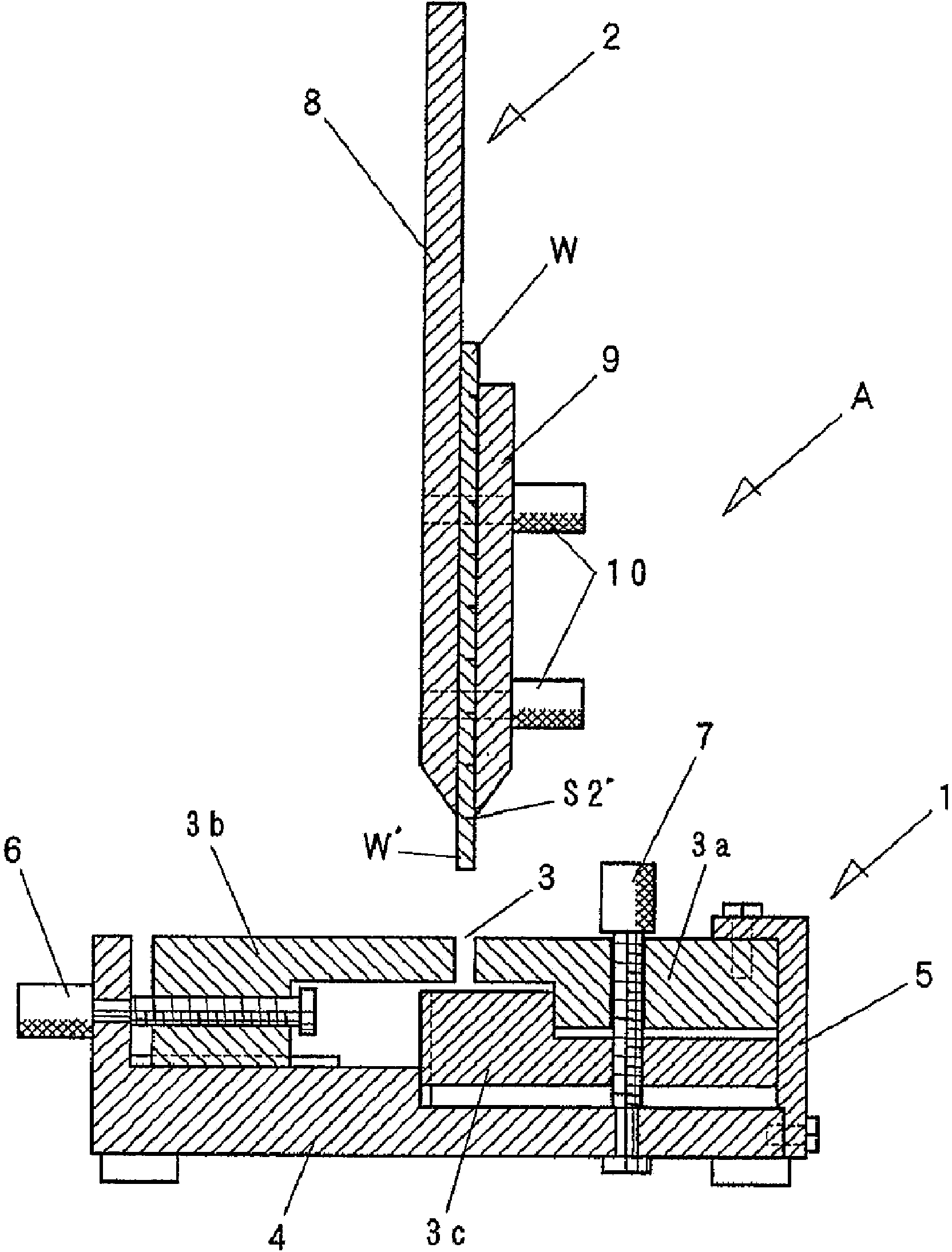
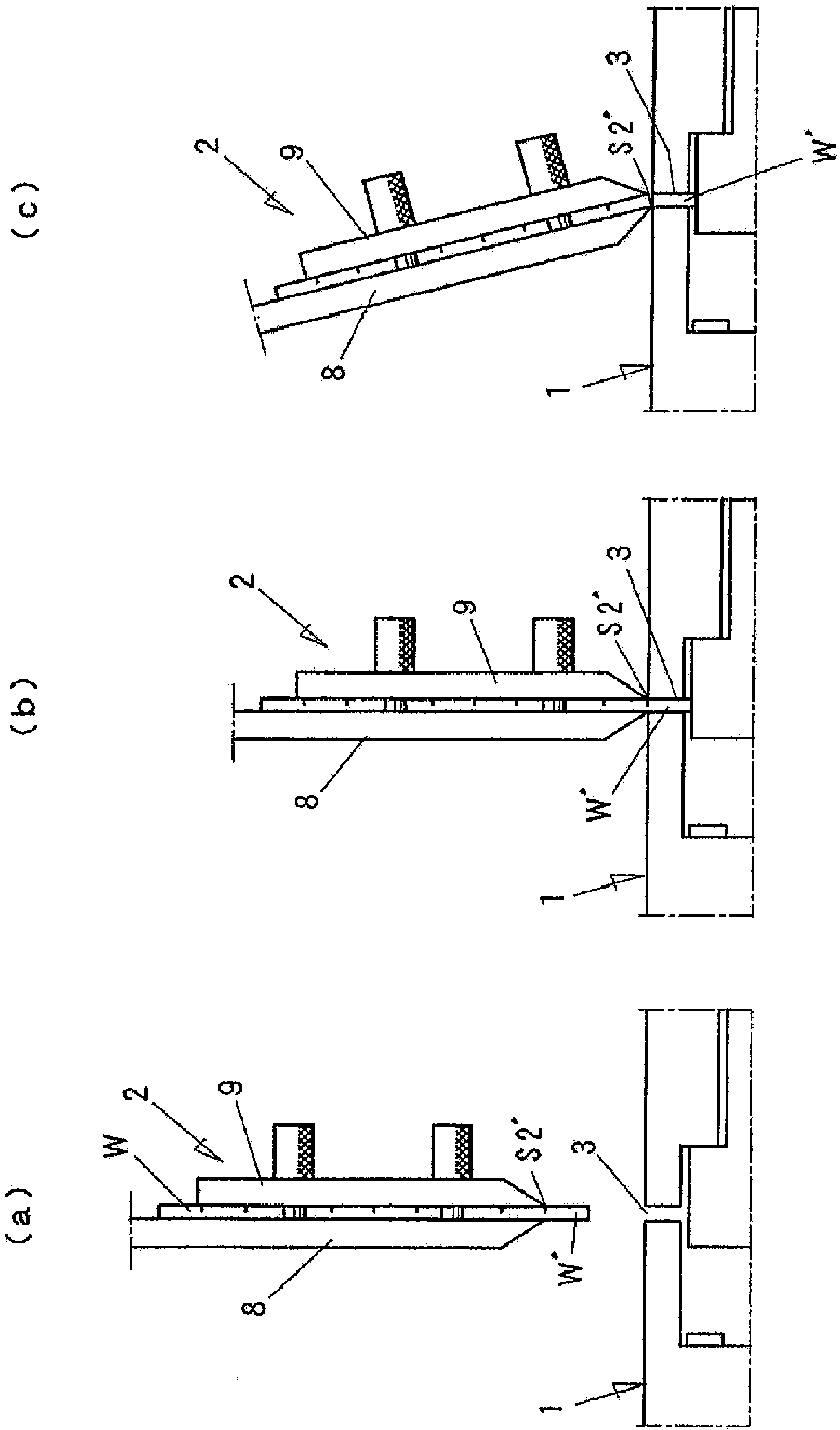
[0050] Below, based on Figure 1-11 The cutting tool of the present invention will be described in detail.

[0051] The cutting tool A of the present invention includes: a support jig 1 having a linear groove 3 on the surface into which one end portion of the substrate W is inserted; ( figure 1 The substrate W is sandwiched and held in a state where the lower end of the substrate W protrudes. Figure 1~3 is a drawing related to the clamping jig of the first embodiment, Figure 4~6 is a drawing related to the insertion jig of the second embodiment, Figure 7-10 It is a figure related to the insertion jig of 3rd Embodiment.

[0052] The support fixture 1 includes: a fixed side wall part 3a forming one side wall of the groove 3; a movable side wall part 3b forming the other side wall; a movable bottom plate part 3c forming the bottom surface of the groove 3; and a workbench 4 , keep these components.

[0053] The fixed side wall member 3 a is fixed to the table 4 via the s...


PUM


Abstract

The invention refers to a brittle material base board parting tool and a brittle material base board supporting fixture. The parting tool comprises a supporting clamp (1) provided with a groove (3) on a surface used for inserting an end part (W ') of a substrate (W); and a clamp (2) used for clamping and keeping the substrate (W) under the condition of projecting the end part (W ') of the substrate (W) which includes lineation and should be disconnected. The clamp (2) includes a first panel(8), a second panel (9), and an intermediate panel (11) between the panels (8,9) and the substrate (W). The intermediate panel (11) includes elastic materials; a left and ring width (L1) of the intermediate panel (11) is smaller than a left and right width (L2) of the substrate (W); an area (L3) without stacked intermediate panels (11) are left on left and right ends of the clamped substrate (W).

Description

technical field [0001] The invention relates to a cutting tool for brittle material substrates such as ceramics. In particular, the present invention relates to a simple cutting tool for manually cutting a brittle material substrate (hereinafter, simply referred to as "substrate") on which scribe lines (grooves) have been formed in a previous step. Background technique [0002] Conventionally, a method is known in which scribing equipment such as a cutter wheel (also referred to as a scribing wheel) or a laser beam is used to form scribing lines perpendicular to each other in the X direction and Y direction on the surface of a substrate, and then, from the scribing line The substrate is cut into unit substrates by applying an external force to the surface on the opposite side of the substrate, or bending the substrate, as disclosed in Patent Document 1, Patent Document 2, and Patent Document 3, for example. [0003] In addition, various methods have been conventionally know...

Claims


Application Information

Patent Timeline
Patent Type & Authority Applications(China)
IPC IPC(8): B28D5/00B28D7/04
CPCB23K26/38C03B33/033C03B33/037C03B33/082C03B33/091C03B33/10Y02P40/57
Inventor 木下知子村上健二武田真和音田健司
Owner MITSUBOSHI DIAMOND IND CO LTD
Why Eureka
Try Eureka