Card connector

A card connector, card insertion technology, applied in the direction of connection, contact parts, coupling devices, etc., can solve the problems of difficulty in ensuring contact pressure, the spring pressure of the spring body is not increased, and the contact reliability cannot be expected to be improved, so as to prevent transient interruptions. , the effect of high contact reliability

Inactive Publication Date: 2014-12-31
SMK CO LTD
View PDF7 Cites 0 Cited by
  • Summary
  • Abstract
  • Description
  • Claims
  • Application Information

AI Technical Summary

Problems solved by technology

[0009] However, in the conventional card connector as described above, in the case where only the front end portion of the elastic contact piece is formed into a fork-shaped contact, by providing a plurality of contact portions, it can be expected that it is resistant to foreign objects. Contact reliability, but since resonance depends on the natural vibration number of the elastic contact piece, there is a problem that it cannot be expected to improve the contact reliability with respect to the momentary interruption caused by resonance
[0010] On the other hand, when the elastic contact portion is constituted by a plurality of spring bodies arranged in parallel in the width direction of the connector, since one elastic contact portion is constituted by a plurality of spring bodies arranged in parallel in the width direction of the connector, The plate width of each spring body has to be reduced correspondingly, and thus there is a problem that the spring pressure of each spring body is not increased, and it is difficult to ensure sufficient contact pressure against the card.

Method used


Image

  • Card connector
  • Card connector
  • Card connector

Examples


Embodiment Construction

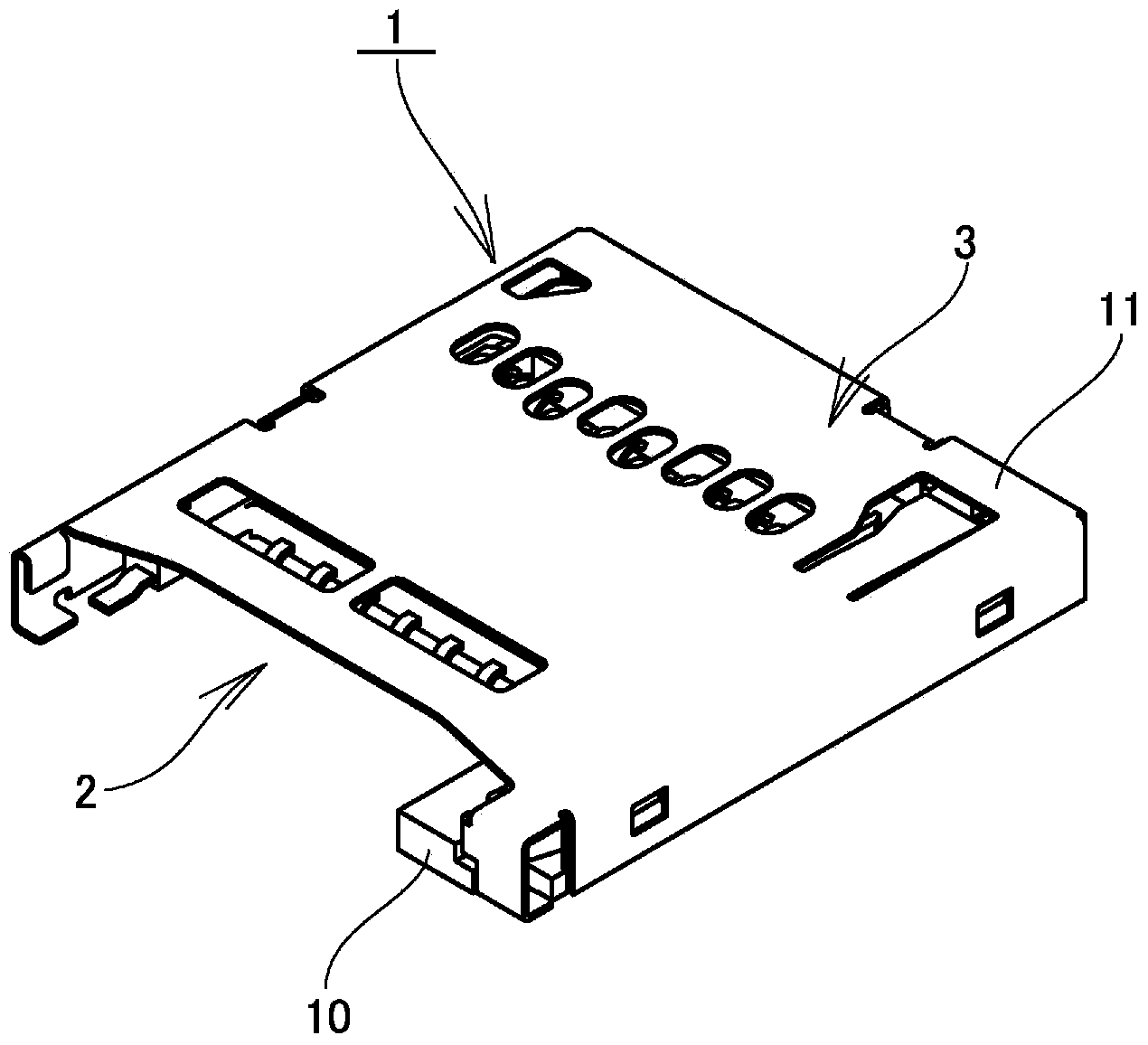
[0030] Below, the embodiment of the card connector of the present invention is based on Figure 1 to Figure 7 The example shown is described. In addition, reference numeral A in the figure is a card such as a flash memory card, and reference numeral 1 is a card connector.

[0031] Card connector 1 is provided with: have the housing 3 of the card insertion part 2 of inserting card A; 2, when the card A is inserted, the pads 6, 6... arranged on one side of the card A come into contact with the corresponding contacts 5, 5..., thereby electrically connecting the mounting substrate on which the card connector 1 is mounted. with card A.

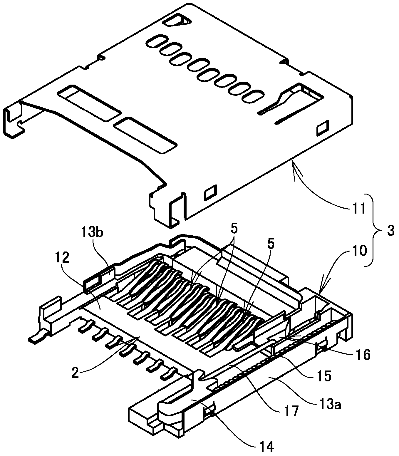
[0032] Such as figure 2As shown, the housing 3 is formed into a hollow box shape with an opening on the front side in the card insertion direction by combining the housing body 10 and the shielding cover 11 made of conductive metal material covering the upper surface, the rear surface and the side surface.

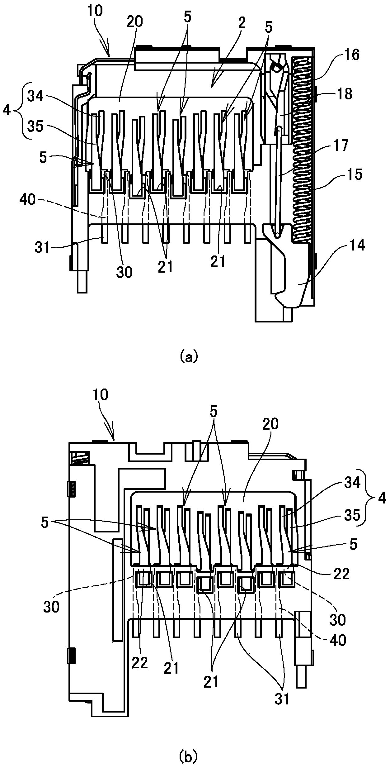
[0033] Such as image 3 As shown, ...


PUM


Abstract

The invention provides a card connector which can ensure full contact pressure relative to a card and prevent transient interruption caused by foreigner matters or resonance. The card connector is provided with a plurality of contacts (5,5...) prepared by conductive metal materials; the contacts project from an inner bottom surface of a card inserting part (2) and are configured on elastic contact parts (4) contacting with pads (6,6...) on a surface of a card (A). The elastic contact parts are provided with a plurality of elastic springs (34,35) in different shapes, respectively provided with inclined sheets (32,33), and stacked at intervals up and down; front end portions of the inclined sheets (32,33) mutually form a plurality of fork shapes, and the inclined sheets are parallelly provided with pad contacts (36,37) in card width directions; when a card is inserted into the card inserting part, the elastic springs (34,35) are pushed by the card to allow the inclined sheets (32,33) stacked up and down to contact mutually; all pad contacts (36,37) of the elastic contact parts (4) are respectively in contact with corresponding pads (6).

Description

technical field [0001] The present invention relates to a card connector for connecting a card such as an IC card or a flash memory card to electronic equipment such as a mobile phone or a smart phone. Background technique [0002] In this card connector, possess: have the housing of the card insertion part that inserts the card such as IC card; Each pad on one side of the card is in contact with the corresponding contact, and the mounting substrate and the card are electrically connected via the card connector. [0003] In the past, the known card connector has the following structure: if the foreign matter attached to the card is attached to the contact at the front end of the elastic contact piece, it will be insulated due to the foreign matter, which may cause damage to the connection between the card and the card connector. Therefore, the contact portion at the front end of the elastic contact piece is formed in a fork shape and has a plurality of contacts to improve c...

Claims


Application Information

Patent Timeline
Patent Type & Authority Applications(China)
IPC IPC(8): H01R13/24H01R12/71
Inventor 镰谷裕康
Owner SMK CO LTD
Why Eureka
Try Eureka