Electric power transmitting device, non-contact power supply system, and control method
A power transmission, non-contact technology, applied in the direction of electromagnetic wave system, transmission system, near-field transmission system, etc., can solve the problems of transmission characteristic change, resonance frequency deviation of resonant circuit, etc., achieve the effect of suppressing the scale of the circuit and improving the transmission efficiency
- Summary
- Abstract
- Description
- Claims
- Application Information
AI Technical Summary
Problems solved by technology
Method used
Image
Examples
Embodiment 1
[0118]
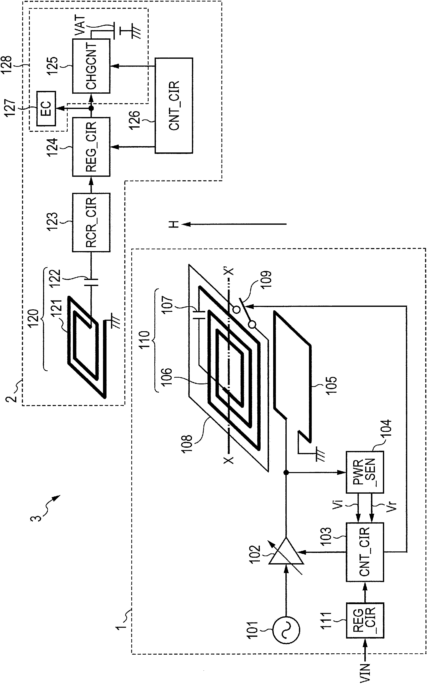
[0119] figure 1 A non-contact power supply system including a power transmission device according to Embodiment 1 is illustrated. A non-contact power supply system 3 illustrated in the figure includes a power transmitting device 1 and a power receiving device 2 . In the non-contact power supply system 3 , it is possible that power supply from the power transmitting device 1 to the power receiving device 2 is in a non-contact manner (wirelessly). Although not particularly limited, in the non-contact power supply system 3 , non-contact power transmission is realized by a magnetic resonance method utilizing resonance coupling of an electromagnetic field. For example, in contactless power transmission, the frequency of a power transmission signal (power transmission frequency) output as power to be transmitted is a frequency in the several MHz region.
[0120]
[0121] For example, the power transmission device 1 is configured with an oscillator 101, a transmission ...
Embodiment 2
[0168] Figure 5 A power transmission device according to Embodiment 2 is illustrated.
[0169] Figure 5 The power transmission device 4 illustrated in is different from the power transmission device according to Embodiment 1 in that a plurality of switchable coils are provided for adjusting the resonance frequency of the resonance circuit 110 . exist Figure 5 In the power transmission device 4 illustrated in , the same reference numerals are attached to the same components as those of the power transmission device 1 , and detailed explanations thereof are omitted.
[0170] The power transmitting device 4 is provided with a plurality of switchable coils. Figure 5 A case is illustrated in which the power transmitting device 4 is provided with four switchable coils 201 - 204 ; however, the number of switchable coils is not particularly limited.
[0171] Each of the switchable coils 201-204 can be individually controlled to connect or disconnect the connection state of bot...
Embodiment 3
[0183] Another example of the configuration of a plurality of switchable coils for adjusting the resonance frequency of the transmitting end is described below.
[0184] Figure 8 A configuration example of a switchable coil according to Embodiment 3 is illustrated.
[0185] As illustrated in the figure, a plurality of switchable coils 108_1 - 108_n (n is an integer equal to or greater than 2) are arranged around the resonant coil 106 .
[0186] Each of the switchable coils 108_1-108_n can be individually controlled to connect or disconnect the connection state of both ends thereof. Specifically, the changeover switch 109_1 is coupled between one end and the other end of the switchable coil 108_1, and by setting the changeover switch 109_1 to "ON" or "OFF", both ends of the switchable coil 108_1 are set in a connected state ( short circuit) or disconnected state (open circuit). Similarly, a changeover switch 109_2 is coupled between one end of the switchable coil 108_2 and ...
PUM
 Abstract
Description
Claims
Application Information
 - R&D
- Intellectual Property
- Life Sciences
- Materials
- Tech Scout
- Unparalleled Data Quality
- Higher Quality Content
- 60% Fewer Hallucinations
Browse by: Latest US Patents, China's latest patents, Technical Efficacy Thesaurus, Application Domain, Technology Topic, Popular Technical Reports.
© 2025 PatSnap. All rights reserved.Legal|Privacy policy|Modern Slavery Act Transparency Statement|Sitemap|About US| Contact US: help@patsnap.com


