Box body lifting structure of storage cabinet

A lifting structure and storage cabinet technology, applied in cabinets, adjustable cabinets, household appliances, etc., can solve the problems of inconvenient operation and inability to place items on storage racks, and achieve convenient operation, small external space, and good structure simple effect

Active Publication Date: 2015-01-07
嘉善县临沪新城实业有限公司
View PDF8 Cites 11 Cited by
  • Summary
  • Abstract
  • Description
  • Claims
  • Application Information

AI Technical Summary

Problems solved by technology

In order to ensure safety, the locker needs to be equipped with a cabinet lock, which brings some inconvenience to the operation, and no items can be placed under the storage rack, otherwise there will be no space for the lift locker to descend

Method used


Image

  • Box body lifting structure of storage cabinet
  • Box body lifting structure of storage cabinet
  • Box body lifting structure of storage cabinet

Examples


Embodiment 1

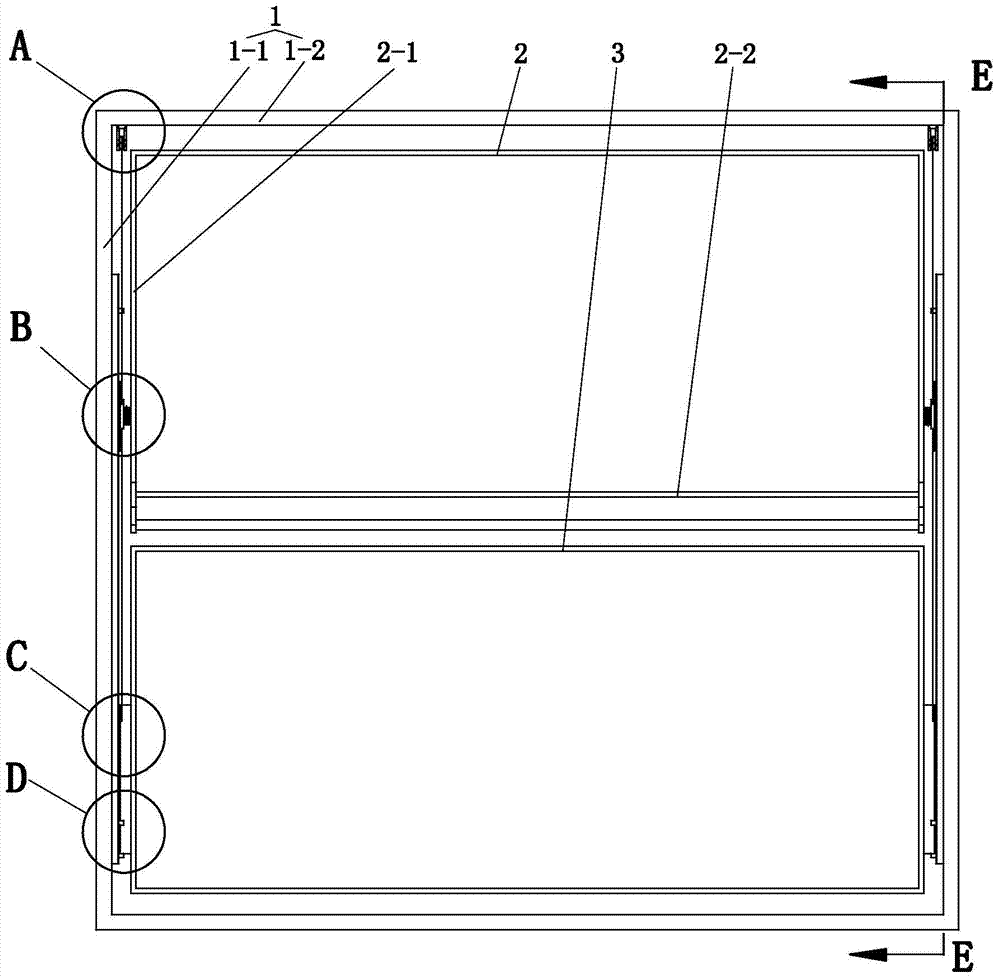
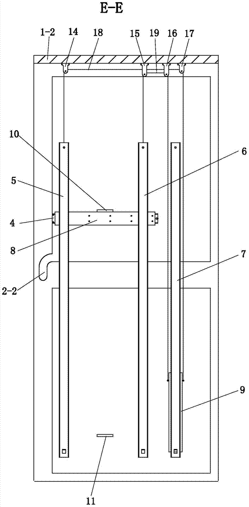
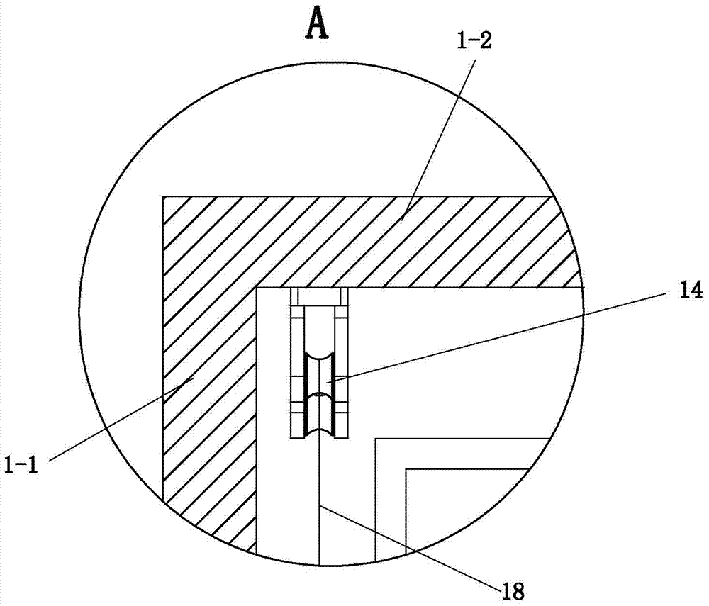
[0025] See Figure 1 to Figure 11 , The cabinet lifting structure of the locker in this embodiment has a cabinet body 1 and an active cabinet body 2 and a passive cabinet body 3 inside the cabinet body 1 . The active box body 2 is provided with a handle 2-2. The inboards of the left and right cabinet boards 1-1 of the cabinet body 1 respectively have a front vertical slide rail 5, a middle vertical slide rail 6, a rear vertical slide rail 7 and a horizontal telescopic slide rail 4.

[0026] The distance between the front vertical slide rail 5 and the middle vertical slide rail 6 is relatively large. The front vertical slide rail 5, the middle vertical slide rail 6, and the rear vertical slide rail 7 have the same structure, all of which have a vertical guide groove S and a vertical slide bar T matching the vertical guide groove S. There is a ball Q between the vertical guide groove S and the vertical guide bar T, and the ball Q is supported by the ball support Q-1 (see Fig...

Embodiment 2

[0034] See Figure 12 , the present embodiment is not to limit the stroke of the front lifting plate, but to limit the stroke of the rear lifting plate, so the magnetic upper and lower limit blocks of the front lifting plate are not provided. On the inner sides of the two cabinet boards 1-1 on the left and right of the cabinet body 1 and at the upper limit position of the rear lifting plate, a rear lifting plate magnetic upper limit block 12 is respectively provided, and a rear lifting plate magnetic upper limit block 12 is respectively provided at the lower limit position of the rear lifting plate. Lifting plate magnetic lower limit block 13. When the lower end of the rear lifting plate 9 hits the magnetic lower limit block 13 of the rear lifting plate, or the upper end surface of the rear lifting plate 9 touches the magnetic upper limit block 12 of the rear lifting plate, stop pulling (pushing) the active box body 2 . All the other are identical with embodiment 1.


PUM


Abstract

A box body lifting structure of a storage cabinet comprises cabinet bodies, a driving box body and a driven box body; the inner side of a left cabinet plate of the corresponding cabinet body and the inner side of a right cabinet plate of the corresponding cabinet body are provided with a front vertical sliding rail, a middle vertical sliding rail, a rear vertical sliding rail and a horizontal extensible sliding rail respectively; a vertical guide groove of every vertical sliding rail is fixed in the inner lateral side of the corresponding cabinet plate of the corresponding cabinet body; a front lifting plate is fixed between vertical sliding strips of each front vertical sliding rail and the corresponding middle vertical sliding rail; a rear lifting plate is fixed on a vertical sliding strip of each rear vertical sliding rail; a horizontal guide groove of each horizontal extensible sliding rail is fixed in the corresponding front lifting plate; the driving box body is connected between horizontal sliding strips of the horizontal extensible sliding rails which are arranged on the bilateral sides respectively; the driven box body is connected between the rear lifting plates which are arranged on the bilateral sides respectively; a top plate of each cabinet body is provided with a front pulley, a middle pulley, a rear pulley and two rear pulleys. According to the box body lifting structure of the storage cabinet, the driven box body automatically slides upward when the driving box body slides downward, the transposition of the driving box body and the driven box body can be achieved, and accordingly the fetch is convenient.

Description

technical field [0001] The invention relates to a box lifting structure of a locker. Background technique [0002] In the daily life of the family, in order to effectively use the indoor space, people will use the high places such as wardrobes or storage rooms as the space for placing some infrequently used items. When placing or taking them out, they often need to climb up with the help of ladders or benches. , especially for the disabled and the elderly is very inconvenient and dangerous. At present, in order to meet the requirements for accessing items at high places, many related products have also appeared. [0003] For example, the Chinese invention patent "Variable Load Adjustable Lifting Locker" with the authorized notification number CN1188067C discloses a variable load adjustable lifting locker, including lockers, storage racks, left and right parallel linkages and left and right lifting controls. It is assembled on the main shaft fixedly connected with the activ...

Claims


Application Information

Patent Timeline
IPC IPC(8): A47B51/00
CPCA47B51/00
Inventor 沈洪雷栗慧曹霞王立宇
Owner 嘉善县临沪新城实业有限公司
Why Eureka
Try Eureka