Limiting and stabilizing structure of drawer sliding rail

A technology for stabilizing structures and drawers, applied in drawers, furniture parts, household appliances, etc., can solve problems that affect the service life of drawers, the gear shaft is easy to be bent, and the guide rail movement is not smooth, etc., to achieve a simple and reasonable structure, pull Smooth, reliable results

Inactive Publication Date: 2015-01-07
伍志勇
View PDF5 Cites 2 Cited by
  • Summary
  • Abstract
  • Description
  • Claims
  • Application Information

AI Technical Summary

Problems solved by technology

The gear of this structure is connected to the side wall of the middle rail through the rotation of the gear shaft. Since the gear shaft is in a cantilever structure, when the drawer bears load, the gear shaft is easily bent, resulting in unsmooth movement of the guide rail. The greater the force received, the teeth of the gears are prone to detachment or toothing due to the pull of the drawer, resulting in damage to the gears and affecting the service life of the drawer

Method used


Image

  • Limiting and stabilizing structure of drawer sliding rail
  • Limiting and stabilizing structure of drawer sliding rail
  • Limiting and stabilizing structure of drawer sliding rail

Examples


no. 1 example

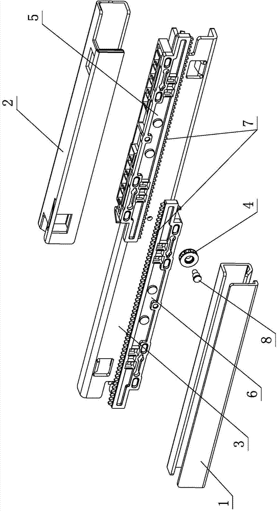
[0041] see Figure 1-Figure 4 , the position-limiting and stable structure of the drawer slide rail includes a fixed rail 1 arranged on the main body of the furniture, a movable rail 2 arranged on the furniture drawer, and an intermediate rail arranged between the fixed rail 1 and the movable rail 2. rail 3, the three rails are slidingly connected to each other through the synchronous wheel 4, the synchronous wheel 4 is made of plastic, and is rotatably arranged on the middle rail 3, and slidingly arranged between the fixed rail 1, the movable rail 2 and the middle rail 3 In the sliding bracket assembly, the synchronous wheel 4 acts on the fixed rail 1, the movable rail 2, and / or the sliding bracket assembly; the synchronous wheel 4 is a gear plate structure with the functions of both limiting and increasing strength.

[0042] Specifically, the sliding bracket assembly includes a first sliding bracket 5 and a second sliding bracket 6 respectively arranged between the movable r...

no. 2 example

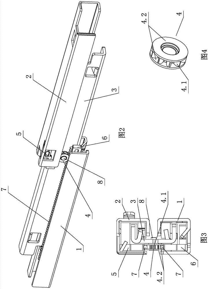
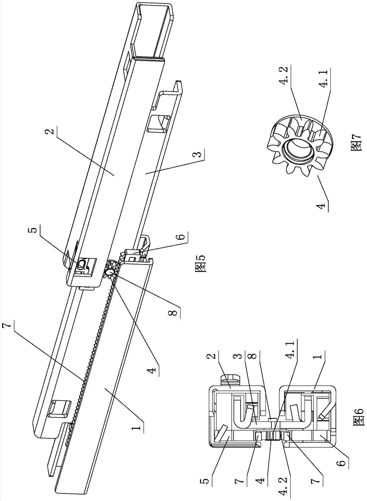
[0049] see Figure 5-Figure 7 , the position-limiting and stable structure of the drawer slide rail is different from the first embodiment in that: the right side of the gear part 4.1 is provided with a position-limiting reinforced part 4.2 which has both position-limiting and strength-increasing functions, and the right side of the synchronous wheel 4 The side passes through the gear part 4.1 to cooperate with the limit reinforcement part 4.2 to form a right closed disc shape.

[0050] Others are not described in the first embodiment.

no. 3 example

[0052] see Figure 8-Figure 10 , the position-limiting and stable structure of the drawer slide rail is different from the first embodiment in that: the left side of the gear part 4.1 is provided with a position-limiting reinforcing part 4.2 which has both position-limiting and strength-increasing functions, and the left side of the synchronous wheel 4 The side passes through the gear part 4.1 to cooperate with the limit reinforcement part 4.2 to form a left closed disc shape.

[0053] Others are not described in the first embodiment.


PUM


Abstract

The invention provides a limiting and stabilizing structure of a drawer sliding rail. The limiting and stabilizing structure comprises an immobile rail arranged on a furniture main body, a movable rail arranged on a furniture drawer, and a middle rail arranged between the immobile rail and the movable rail; the three rails are slidingly connected with each other by use of a synchronizing wheel which is made of plastics and rotatably arranged on the middle rail; sliding support assemblies are arranged between the immobile rail and the movable rail, and the middle rail; the synchronizing wheel acts on the immobile rail and the movable rail, and / or the sliding support assemblies; the synchronizing wheel is of a gear disc structure having both limiting and strength enhancing effects. The limiting and stabilizing structure of the drawer sliding rail has the characteristics of simple and reasonable structure, reliable performance, low manufacturing cost, steady and smooth drawing, low noise, long service life and the like, and is highly practical.

Description

technical field [0001] The invention relates to a drawer slide rail, in particular to a position-limiting and stable structure of the drawer slide rail. Background technique [0002] Chinese Patent Document No. CN101554273 disclosed an integrated drawer rail on October 14, 2009, which includes a lower rail, a middle rail, an upper rail, front corners, rear corners, pallets, side panels, panel connecting devices and buffers; It is characterized in that there is a rack on the cage, and a gear on the middle rail; the rack on the cage between the lower rail and the middle rail is parallel to the rack on the cage between the middle rail and the upper rail, and they are all parallel to each other. gears meshing. The gear of this structure is connected to the side wall of the middle rail through the rotation of the gear shaft. Since the gear shaft is in a cantilever structure, when the drawer bears load, the gear shaft is easily bent, resulting in unsmooth movement of the guide ra...

Claims


Application Information

Patent Timeline
Patent Type & Authority Applications(China)
IPC IPC(8): A47B88/04A47B88/08A47B88/49
CPCA47B88/447
Inventor 伍志勇
Owner 伍志勇
Why Eureka
Try Eureka