Threaded-rod type puller provided with adjustable reach distance device

A screw-type, adjusting column technology, applied in the field of pullers, can solve the problems of increased difficulty, inconvenient use, deviation from the center of the pulled object, etc., and achieves the effects of a wide range of applications, convenient manufacturing and convenient use.

Inactive Publication Date: 2016-06-01
苗洪敏
View PDF0 Cites 2 Cited by
  • Summary
  • Abstract
  • Description
  • Claims
  • Application Information

AI Technical Summary

Problems solved by technology

[0003] The extension range of the existing three-claw screw type puller is determined by the diameter of the circle where the three pull feet are located, and the extension distance is determined by the length of the pull feet and the screw rod. With the rotation of the screw rod, the pull feet and the pulled The angle of the surface of the object to be picked will change, and it is easy to slip or the screw rod deviates from the center of the object to be pulled, or even damage the object to be pulled; and in order to ensure the stability of the puller, the extension of the puller with a certain extension range is also limited. That is to say, one puller has poor versatility for objects of different depths. Usually, multiple pullers are needed to complete a type of work, and the work efficiency is low and the workload is heavy.
[0004] In order to solve the above-mentioned deficiencies, a puller disclosed in Chinese Patent No. CN2013102484298 Patent Application for Invention includes a puller foot, a puller seat and a screw mandrel. Each base is provided with a guide rail groove, and the pull foot stretches back and forth in the guide rail groove, which can individually adjust the extension distance and extension distance, so that the pull foot and the surface of the object to be pulled are always kept in a vertical state to ensure stable pulling; the above patent Although the extension distance can be extended according to the needs, it has good versatility for parts of different depths, but it is inconvenient to adjust each pull foot during use, and its structure is extremely complicated due to the use of guide rail grooves and threaded hole structures in many places , increasing the difficulty of manufacturing and increasing the cost of manufacturing

Method used


Image

  • Threaded-rod type puller provided with adjustable reach distance device
  • Threaded-rod type puller provided with adjustable reach distance device

Examples


Embodiment Construction

[0018] The present invention will be further described below in conjunction with the accompanying drawings:

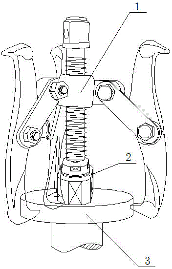
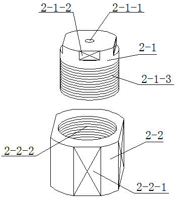
[0019] like Figure 1-2 As shown, a screw-type puller with an adjustable extension device includes a puller main body 1, an adjustable extension device 2 is connected to the main body 1 of the puller, and the adjustable extension device 2 is arranged on the puller Between the main body 1 and the object to be pulled 3, the adjustable extension device 2 is composed of an upper adjustment column 2-1 and a lower adjustment column 2-2.

[0020] like figure 2 As shown, the extension device is composed of an upper adjustment column and a lower adjustment column. The material used for the upper and lower adjustment columns is medium carbon steel. The outer surface of the upper adjustment column has external threads 2-1-3, and the inner surface of the lower adjustment column has There are internal threads 2-2-2, both external threads and internal threads are coarse-tooth tri...


PUM


Abstract

The invention provides a puller. The puller comprises a puller body. The puller body is connected with an adjustable reach distance device. The adjustable reach distance device is arranged between the puller body and a pulled object. The adjustable reach distance device is formed by combining an upper adjusting pillar with a lower adjusting pillar. The adjustable reach distance device can adjust the reach distance of a threaded rod, so that a pulling foot and the surface of the pulled object keep in the perpendicular state all the time. By means of the threaded-rod type puller, pulling stability is guaranteed; universality for parts at different depths is good; and the puller is high in work efficiency and wider in application scope.

Description

technical field [0001] The invention relates to a puller, in particular to a screw type puller with an adjustable extension device. Background technique [0002] The puller is also called the jack puller, which is widely used to disassemble various fastening parts such as couplings, gears, bearings, pulleys, etc. According to the number of puller claws, it is usually divided into two-claw type and three-claw type; The method is usually divided into screw type and jack type puller; the three-jaw screw type puller is the most widely used. There is a push head at the bottom of the screw. When in use, the claw hooks the object to be pulled, and the driving cap on the top of the push screw is rotated, so that the push screw rotates and advances smoothly. The claw moves backward relative to the push screw and will be pulled Pull the object out. [0003] The extension range of the existing three-claw screw type puller is determined by the diameter of the circle where the three pu...

Claims


Application Information

Patent Timeline
Patent Type & Authority Applications(China)
IPC IPC(8): B25B27/02B25B27/073
Inventor 苗洪敏
Owner 苗洪敏
Why Eureka
Try Eureka