
Strip rolling variable crown roll having local edge wave control capability

A controllable, variable crown technology, used in contour control, roll, metal rolling, etc.

Active Publication Date: 2015-01-07
UNIV OF SCI & TECH BEIJING
View PDF4 Cites 15 Cited by
  • Summary
  • Abstract
  • Description
  • Claims
  • Application Information

AI Technical Summary

Problems solved by technology

This problem is also a common problem that tends to occur in wide-band steel and ultra-wide-band steel six-high CVC cold rolling mills

Method used


Image

  • Strip rolling variable crown roll having local edge wave control capability
  • Strip rolling variable crown roll having local edge wave control capability
  • Strip rolling variable crown roll having local edge wave control capability

Examples


Embodiment Construction

[0071] The technical solutions of the present invention will be further described below in conjunction with the embodiments.

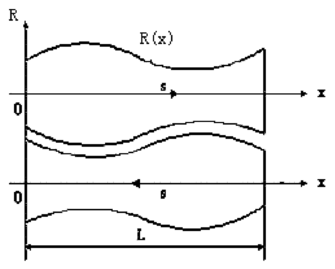
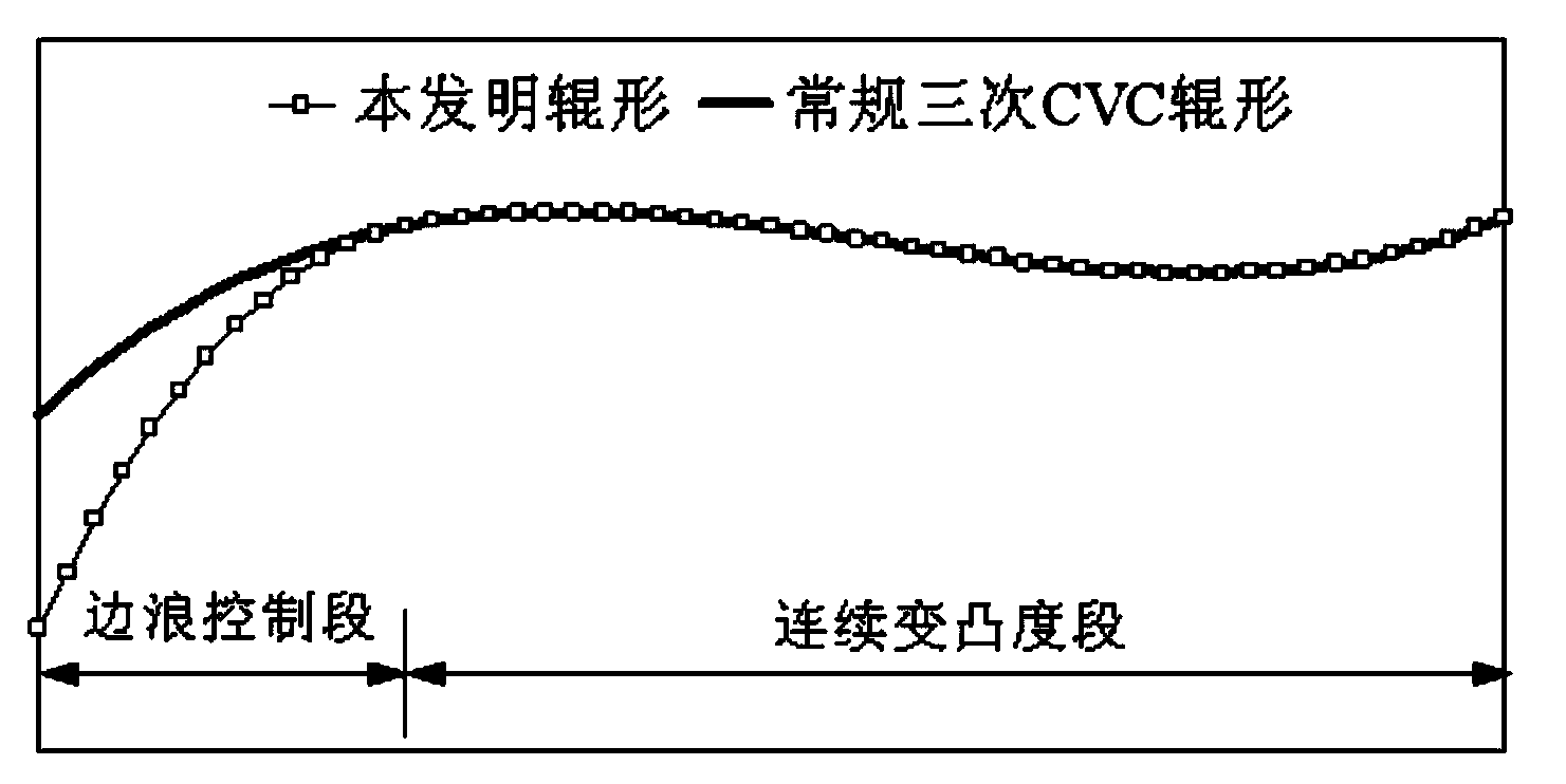
[0072] A variable crown roll with local edge wave control capability, characterized in that the roll shape curve is composed of an edge wave control section and a continuous variable crown section. First, the end of the edge wave control section of the roll body is taken as the coordinate origin Set the roll curve equation as:

[0073] y t 0 ( x ) = R 0 + ( a 1 + a 1 ′ ) ...


PUM


Abstract

The invention provides a strip rolling variable crown roll having the local edge wave control capability. The rolling roll shape is formed by an edge wave control section and a continuous variable crown section. The continuous variable crown section is used for completing secondary crown control in a strip rolling process. The edge wave control section is used for completing the control of local edge waves. The edge wave control effect depends on the depth of the edge wave control section in a strip and the formed maximum effective roller seam difference of strip edges. The roll shape can be flexibly designed according to the needs of the secondary crown control and the control of the local edge waves through the corresponding relationship of coefficients of the roll shape. Furthermore, the effective control of the local edge waves of strips in different widths is achieved by combining the position characteristics of a channeling roll of the variable crown roll shape in different widths of a strip rolling mill.

Description

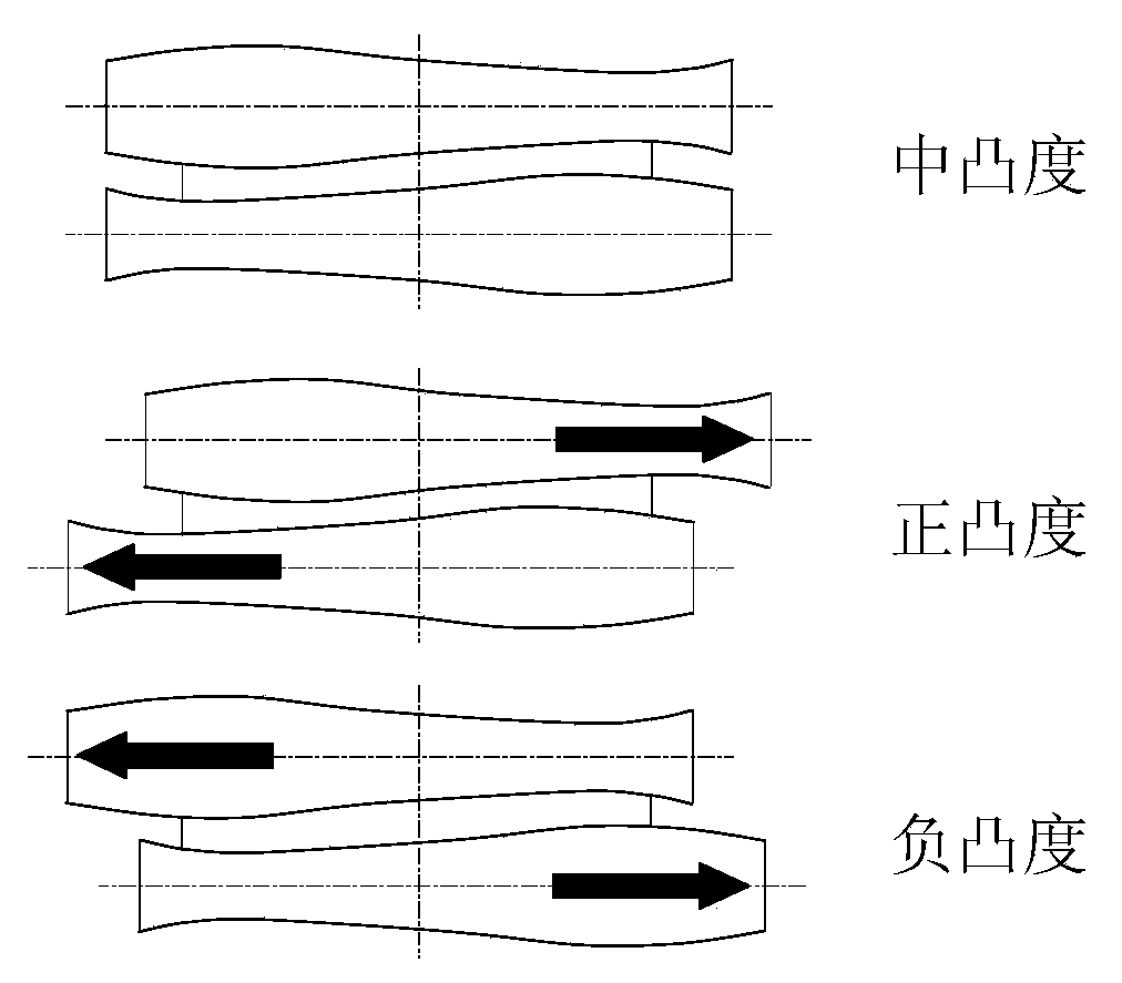
technical field [0001] The invention belongs to the field of strip rolling, and relates to a roll shape design method and control characteristics of a variable crown roll with local edge wave control capability used for strip shape control in strip production. Background technique [0002] The roll shape of the present invention is a variable-convex roll shape with local edge wave control ability developed on the basis of the three-time CVC roll shape. [0003] (1) Triple CVC roll shape [0004] At the end of the 1970s, Germany's SMS company (SMS) took the lead in developing the continuously variable crown (CVC-Continuously Variable Crown) roll shape. After more than 30 years of research and development, the CVC roll shape has become the most advanced in the field of strip rolling. One of the main means of shape control. This technology can continuously change the crown of the unloaded roll gap through the relative axial movement of the rolls, so as to control the shape of...

Claims


Application Information

Patent Timeline
Patent Type & Authority Applications(China)
IPC IPC(8): B21B27/02B21B37/30
Inventor 李洪波张杰包仁人曹建国
Owner UNIV OF SCI & TECH BEIJING
Learn More