Catapult window breaking device

A ejection-type, window-breaking technology, which is applied in transportation and packaging, pedestrian/passenger safety arrangement, vehicle safety arrangement, etc., can solve the problems of large space, short effective force arm, easy loss, etc. The effect of long arm and short start-up time

Active Publication Date: 2016-09-14
SHENZHEN GREENWHEEL ELECTRIC VEHICLE CO LTD
View PDF6 Cites 5 Cited by
  • Summary
  • Abstract
  • Description
  • Claims
  • Application Information

AI Technical Summary

Problems solved by technology

The vehicle-mounted safety hammer that is widely used at this stage is mainly to break the glass with the hammer tip to escape. It has some obvious disadvantages when it is used. First, most people do not know that they should use the safety hammer to hit the corner of the window where the stress is concentrated. And to knock on the window that is not easy to be broken
In addition, on school buses, tourist buses, etc., the upper edge of the window is blocked by the luggage rack, and the lower edge is blocked by the seat, so there is no suitable point of force for hammering the corner of the window, and the window center that is not easy to be broken can only be selected.
The second is that when danger occurs, the car is crowded and crowded, and the user does not have enough space to stretch his arms and enough buffer distance, so that the hammering force is too small to break the glass.
The third is that the safety hammer is placed directly next to the window, which is easy to lose
Fourth, when a safety hammer is used in danger, the hammering force is often not perpendicular to the glass surface, and the direction of the force is inclined at an angle to the glass surface, which greatly reduces the hammering force and makes it difficult to break the glass
Fifth, when an accident occurs, most people will be in panic, worrying that using a safety hammer to hammer the glass will scratch their arms by glass fragments, so when knocking on the window, they may not be able to smash the window quickly due to psychological factors
After model experiments, it is found that its shortcomings are firstly that when the device is fixed on the window frame, because the distance between the glass and the window frame of different models is different, the height of the rivet cannot be adjusted and cannot make it contact with the glass surface, so Can not match various models
The second is that the protruding part of the rivet is too long. On the one hand, when the nail tip is subjected to a force perpendicular to the screw rod, the maximum bending moment generated by the section rigidly connected between the rivet and the screw rod will easily break the rivet. On the other hand, the rivet Too long, increasing the cost
The third is that the upper and lower legs of the torsion spring of this invention are respectively stuck on the rotating arm and the base. In addition, the torsion spring has no other fixing measures. When the rotating arm is pulled up, the legs of the torsion spring are easy to slip and fall off, which is not effective broken window
The fourth is that when the window glass has an inclined angle, the angle of the rotating arm cannot be adjusted accordingly, and the rivet cannot vertically touch the window glass surface
The fifth is that the position of the torsion spring is at the front end of the support, resulting in too short effective arm, and the tension required to overcome the bending moment of the spring increases, so that the elderly, women and children cannot easily pull up the knob, so the window cannot be effectively broken
The sixth is that some car window frames are narrow, and the base of the device protrudes from the support. The base cannot be fixed, and it takes up a lot of space.

Method used


Image

  • Catapult window breaking device
  • Catapult window breaking device
  • Catapult window breaking device

Examples


Embodiment Construction

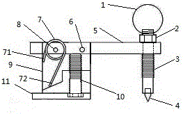
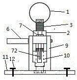
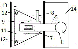
[0024] like figure 1 , 2 , The ejection-type window breaking device shown in 3 is composed of a spherical handle 1, a nut 2, a screw rod 3, a striker 4, a rotating arm 5, a safety pin 6, a torsion spring 7, a pin 8, a bearing 9, an inner hexagon socket screw 10, The triangular base 11 and the screw 12 are characterized in that the spherical handle 1 is threaded and screwed to the upper end of the screw 3, the screw 3 is threaded and the front end of the rotating arm 5 is screwed, the nut 2 is set on the screw 3, and is located between the rotating arm 5 and the spherical In the middle of the handle 1, the rivet 4 is embedded in the lower end of the screw rod 3, the tip of the rivet 4 touches the window glass surface, the rear end of the rotating arm 5 is fixed with the support 9 through the pin 8, and the pin 8 passes through the support 9 and the torsion spring 7 , rotating arm 5, safety pin 6 passes bearing 9, rotating arm 5, and the upper leg 71 of torsion spring is stuck ...


PUM


Abstract

Disclosed is an ejection type window breaking device which is high in starting speed, high in window breaking success rate, not easy to lose, small in occupied space and safe and stable. The ejection type window breaking device is characterized in that a ball handle is hinged to the upper end of a screw through threads; the screw is connected with the front end of a rotating arm through threads in a rotating mode; a nut sleeves the screw and is located between the rotating arm and the ball handle; a rivet is embedded at the lower end of the screw; a pointed end of the rivet abuts against the glass surface of an automobile window; the rear end of the rotating arm and a support are fixed through a pin; the pin penetrates the support, a torsional spring and the rotating arm; a safety pin penetrates the support and the rotating arm; an upper supporting leg of the torsional spring is clamped on the inner wall of the rotating arm; a lower supporting leg of the torsional spring is clamped in a groove formed in the support; the lower end of the support is fixed on a triangular base; a socket head cap screw is connected with the support and the triangular base through threads; the bottom of the socket head cap screw is in contact with the rotating arm; the triangular base is fixed on an automatic window frame through screws.

Description

technical field [0001] The invention relates to the field of motor vehicle safety, in particular to an emergency escape device for a motor vehicle. Background technique [0002] As a necessary escape tool in buses, school buses, etc., safety hammer has been widely adopted and recognized. However, there are many problems in the use of common traditional safety hammers, resulting in that the use of the safety hammer cannot timely and effectively break the window and escape when a dangerous situation occurs. In recent years, when a car has an accident, the situation of losing the chance of escape because the window cannot be opened occurs frequently. The vehicle-mounted safety hammer that is widely used at this stage is mainly to break the glass with the hammer tip to escape. It has some obvious disadvantages when it is used. First, most people do not know that they should use the safety hammer to hit the corner of the window where the stress is concentrated. Instead, knock o...

Claims


Application Information

Patent Timeline
Patent Type & Authority Patents(China)
IPC IPC(8): B60R21/02
CPCB60R21/02B60R2021/0246
Inventor 范雲鹤
Owner SHENZHEN GREENWHEEL ELECTRIC VEHICLE CO LTD
Why Eureka
Try Eureka