Electric control separation mechanism of unmanned aerial vehicle and parachute

A separation mechanism and parachute technology, applied in the directions of parachutes, aircraft parts, transportation and packaging, can solve the problems of unsafe explosive storage, damage and collision of drones or airborne equipment, and achieve simple and practical structural principles and large applications. The effect of strong value and carrying capacity

Inactive Publication Date: 2015-01-07
ZHEJIANG COLLEGE OF ZHEJIANG UNIV OF TECHOLOGY +1
View PDF6 Cites 15 Cited by
  • Summary
  • Abstract
  • Description
  • Claims
  • Application Information

AI Technical Summary

Problems solved by technology

[0002] UAV landing and landing are usually divided into sliding (running) landing and parachute landing. At present, UAV recovery mainly adopts parachute recovery. Under the weather conditions with high wind speed, the parachute landing UAV will be dragged by the parachute , there are many unfavorable postures such as swinging, shaking, and sideslipping, and collisions may occur, which may cause damage to the UAV or airborne equipment
The parachute throwing mechanism when the plane lands generally adopts the electric explosion method at present, which is activated by the touch switch, but there are problems such as unsafe storage of explosives

Method used


Image

  • Electric control separation mechanism of unmanned aerial vehicle and parachute
  • Electric control separation mechanism of unmanned aerial vehicle and parachute
  • Electric control separation mechanism of unmanned aerial vehicle and parachute

Examples


Embodiment Construction

[0014] The present invention will be further described below in conjunction with the accompanying drawings and embodiments. While the invention will be described in conjunction with the preferred embodiments, it will be understood that it is not intended to limit the invention to the described embodiments. On the contrary, the invention is to cover alternatives, modifications and equivalents, which may be included within the scope of the invention as defined by the appended claims.

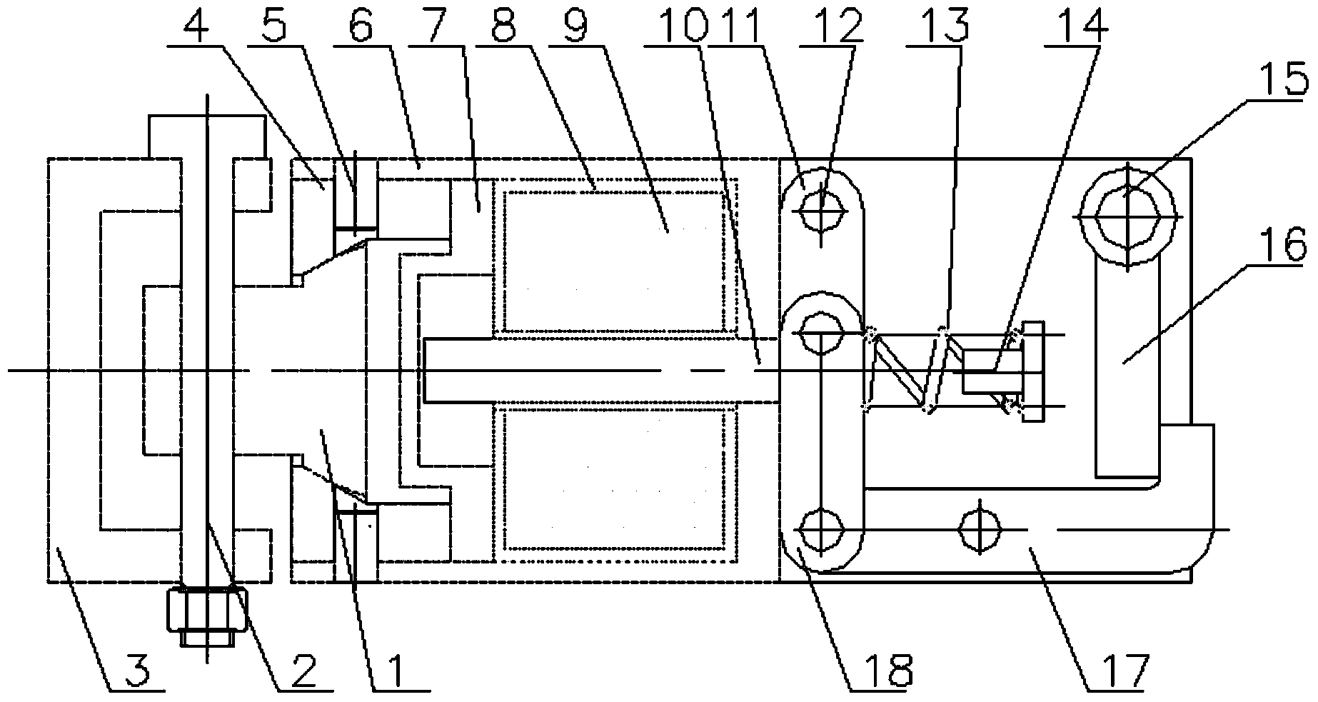
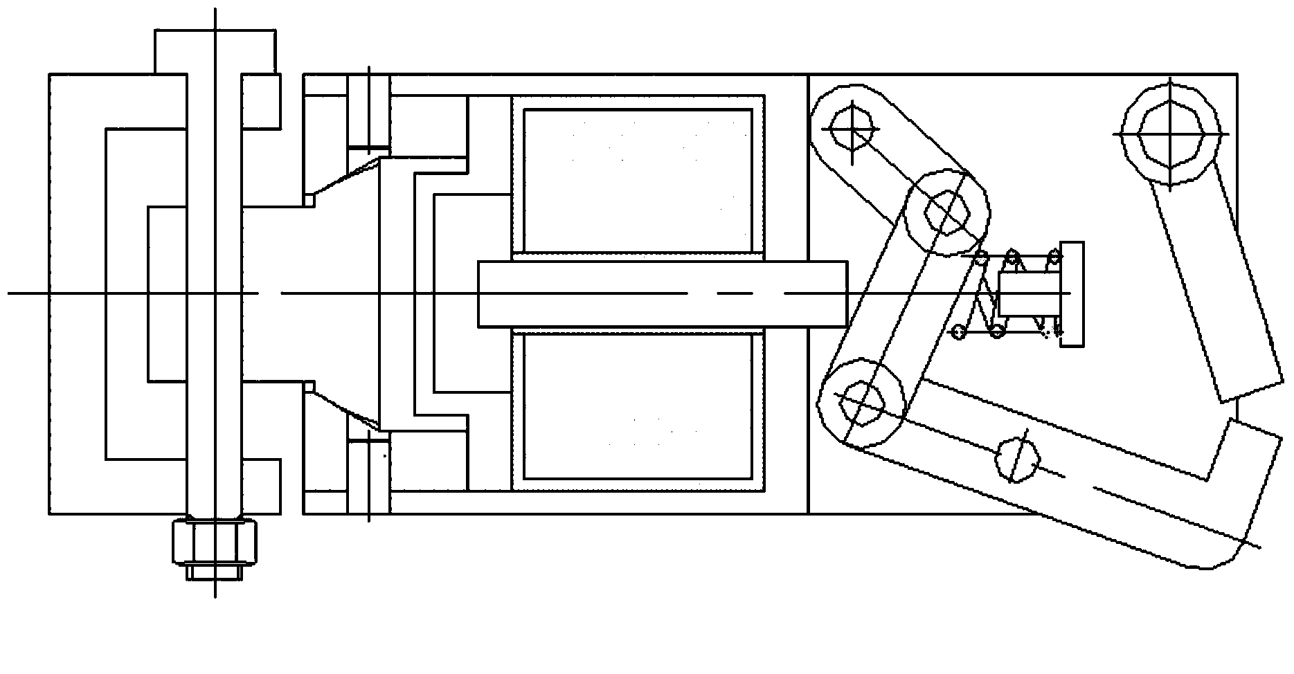
[0015] refer to Figure 1 to Figure 2 As shown, the electronically controlled separation mechanism for the UAV and the parachute in this embodiment consists of three parts: a rotary device, an electromagnet and a locking device. The slewing device adopts the ball-pin slewing pair structure, which is composed of slewing ball head 1, pin shaft 2 and slewing sleeve 3. The head and the end cover 4 are connected in the form of a rotary pair, and the end cover 4 is fixedly connected with the frame 6 t...


PUM


Abstract

The invention discloses an electric control separation mechanism of an unmanned aerial vehicle and a parachute. The electric control separation mechanism comprises a rotary device, an electromagnet and a locking device; when the locking device is located in the locked device, the electromagnet is not electrified, an electromagnet armature does not extend out, a driving rod and a connecting rod form into a straight line, and a driving rod cannot rotate under the action of the tension of the parachute through the position of a dead point of a hinge four-bar mechanism; when the locking device is located in the unlocked state, the electromagnet is electrified, the electromagnet armature extends out, and the driving rod of the hinge four-bar mechanism is pushed to rotate to damage the position of the dead point of the hinge four-bar mechanism. According to the electric control separation mechanism of the unmanned aerial vehicle and the parachute, the large tension of the parachute is borne by components such as the driving rod, the connecting rod and the driven rod of the hinge four-bar mechanism and the components are high in self-strength and bearing capacity; an output thrust value of the electromagnet is small and accordingly the appearance size and the mass of the electromagnet and the electric control separation mechanism can be effectively reduced; the structural principle is simple and practical, the reliability is high, and the application value is large.

Description

technical field [0001] The invention relates to a separation device, in particular to an electronically controlled separation mechanism for a drone and a parachute. Background technique [0002] UAV landing and landing are usually divided into sliding (running) landing and parachute landing. At present, UAV recovery mainly adopts parachute recovery. Under the weather conditions with high wind speed, the parachute landing UAV will be dragged by the parachute , there are many unfavorable postures such as swinging, shaking, and sideslipping, and collisions may occur, which may cause damage to the drone or airborne equipment. The parachute throwing mechanism when the plane lands generally adopts the electric explosion method at present, which is activated by the touch switch, but there are problems such as unsafe storage of explosives. For this reason, need to develop a kind of electric control separating mechanism between the parachute that solves the above problem and the unm...

Claims


Application Information

Patent Timeline
Patent Type & Authority Applications(China)
IPC IPC(8): B64D17/80
Inventor 杨友东童月堂钱少明王吉国胡文杰
Owner ZHEJIANG COLLEGE OF ZHEJIANG UNIV OF TECHOLOGY
Why Eureka
Try Eureka