An isometric displacement bridge expansion joint device
A technology of equidistant displacement and expansion joints, which is applied in bridges, bridge parts, bridge construction, etc., can solve the problem of uniformity and uniformity of the gap between the difficult section steel, and achieve the purpose of changing the uneven gap of the section steel, reducing the difficulty of manufacturing, and simplifying the difficulty of manufacturing Effect
- Summary
- Abstract
- Description
- Claims
- Application Information
AI Technical Summary
Problems solved by technology
Method used
Image
Examples
Embodiment 1
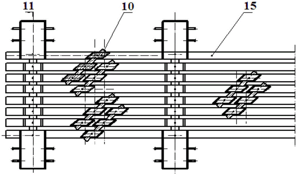
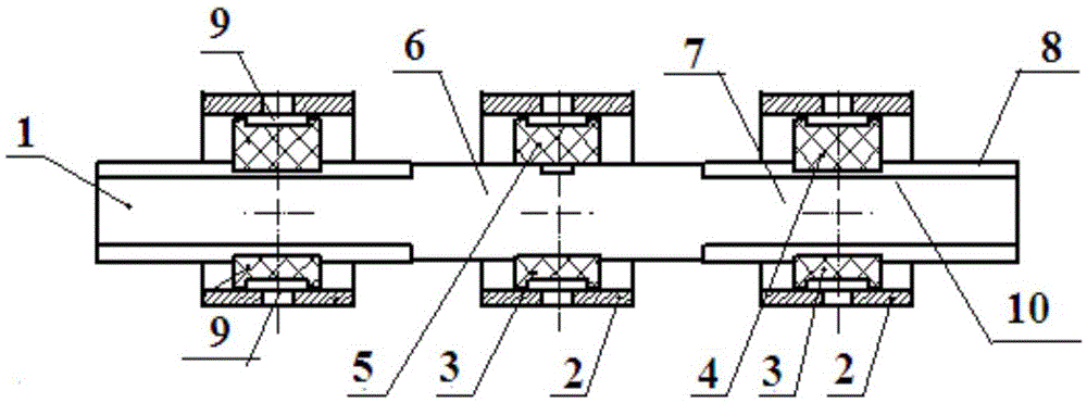
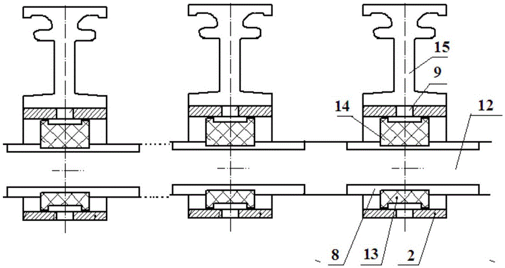
[0016] An equidistant displacement bridge expansion joint device, the device includes a support system 11 and a section steel 15, and the support system 11 and the section steel 15 are vertically connected; the support system 11 includes a support beam 12, a connecting frame 2, and a compression support 14 1. The pressure bearing 13, the pressure bearing 13 and the compression bearing 14 are respectively set in the lower and upper sides of the support beam 12 with a U-shaped structure, and its contact surface is provided with a sliding plate 8 for sliding movement; The seat 14, the pressure bearing 13 and the connecting frame 2 are all connected by the pin shaft 9; the sliding plate 8 is made of stainless steel with cold sprayed zirconia coating; the device also includes a slit width adjustment system 10, the The slit width adjustment system 10 described above is composed of a plurality of slit width adjustment devices, and each slit width adjustment device is obliquely connect...
Embodiment 2
[0018] An equidistant displacement bridge expansion joint device, the device includes a support system 11 and a section steel 15, and the support system 11 and the section steel 15 are vertically connected; the support system 11 includes a support beam 12, a connecting frame 2, and a compression support 14 1. The pressure bearing 13, the pressure bearing 13 and the compression bearing 14 are respectively set in the lower and upper sides of the support beam 12 with a U-shaped structure, and its contact surface is provided with a sliding plate 8 for sliding movement; The seat 14, the pressure bearing 13 and the connecting frame 2 are all connected by the pin shaft 9; the sliding plate 8 is made of stainless steel with cold sprayed zirconia coating; the device also includes a slit width adjustment system 10, the The slit width adjustment system 10 described above is composed of a plurality of slit width adjustment devices, and each slit width adjustment device is obliquely connect...
Embodiment 3
[0020] An equidistant displacement bridge expansion joint device, the device includes a support system 11 and a section steel 15, and the support system 11 and the section steel 15 are vertically connected; the support system 11 includes a support beam 12, a connecting frame 2, and a compression support 14 1. The pressure bearing 13, the pressure bearing 13 and the compression bearing 14 are respectively set in the lower and upper sides of the support beam 12 with a U-shaped structure, and its contact surface is provided with a sliding plate 8 for sliding movement; The seat 14, the pressure bearing 13 and the connecting frame 2 are all connected by the pin shaft 9; the sliding plate 8 is made of stainless steel with cold sprayed zirconia coating; the device also includes a slit width adjustment system 10, the The slit width adjustment system 10 described above is composed of a plurality of slit width adjustment devices, and each slit width adjustment device is obliquely connect...
PUM
 Abstract
Description
Claims
Application Information
 - R&D
- Intellectual Property
- Life Sciences
- Materials
- Tech Scout
- Unparalleled Data Quality
- Higher Quality Content
- 60% Fewer Hallucinations
Browse by: Latest US Patents, China's latest patents, Technical Efficacy Thesaurus, Application Domain, Technology Topic, Popular Technical Reports.
© 2025 PatSnap. All rights reserved.Legal|Privacy policy|Modern Slavery Act Transparency Statement|Sitemap|About US| Contact US: help@patsnap.com


