
Construction technology of slag stacking behind concrete faced rock-fill dam

A technology of face rockfill dam and construction technology, applied in dams, barrages, weirs, etc., can solve the problems of poor physical and mechanical properties, large amount of slag yard protection works, large water catchment, etc., so as to reduce the distance of waste slag transportation , the effect of increasing amusement facilities and beautifying the environment of the dam area

Inactive Publication Date: 2015-01-07
STATE GRID CORP OF CHINA +3
View PDF4 Cites 4 Cited by
  • Summary
  • Abstract
  • Description
  • Claims
  • Application Information

AI Technical Summary

Problems solved by technology

However, not all excavation slag can be used as dam filling materials. The organic components contained in humus soil are unstable, and their physical and mechanical properties are poor; generally, due to severe weathering, the rock mass above the middle part has low strength and physical and mechanical indicators. Poor, the broken materials cannot go to the dam and are discarded. These waste materials need to be accommodated in the waste slag area
Some natural ravines are usually selected as slag dumps for general projects, which brings about a series of problems such as land acquisition and resettlement in the slag area and its connecting roads, long distance of slag transportation, water and soil conservation, and environmental protection. High, steep ditch and large water catchment make the slag field protection work a lot, which is neither economical nor environmentally friendly

Method used


Image

  • Construction technology of slag stacking behind concrete faced rock-fill dam
  • Construction technology of slag stacking behind concrete faced rock-fill dam

Examples


Embodiment 1

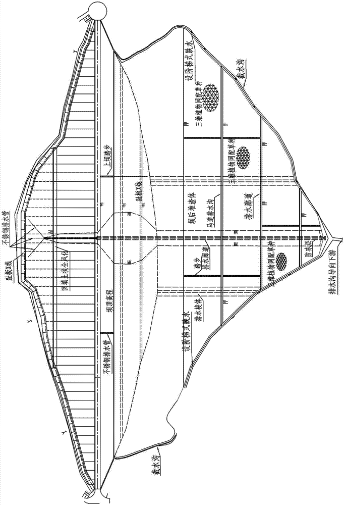
[0015] Below take the large-scale project that has adopted the technical scheme of the present invention as example in conjunction with accompanying drawing to further illustrate: the main dam of the upper reservoir of the Mudanjiang pumped storage power station, the spoil area behind the dam is located within the range line of land expropriation behind the main dam of the upper reservoir, and the main dam On the rear bank slope, within the excavation line of the main dam foundation of the upper reservoir. The main spoil area is located behind the concrete face rockfill dam, where the main dam foundation and revetment excavation, the spoil from the excavation of the stone yard and the excavation spoil of temporary works are mainly stacked, and the spoil volume is about 264×10 4 m 3 , the elevation of the top platform in the spoil area is 640.00m, the top width is 112m, and the downstream side-slope ratio is 1:3.0. Greening and water conservation measures (three-dimensional...


PUM


Abstract

The invention discloses a construction technology of slag stacking behind a concrete faced rock-fill dam and relates to the technical field of water and electricity hydraulic engineering. According to the construction technology of the slag stacking behind the concrete faced rock-fill dam, a waste slag area is arranged behind the concrete faced rock-fill dam, waste slags from main dam foundation, shore protection excavation, quarry excavation and temporary project excavation, the top and side slops of the waste slag area are provided with greening and water protection measures, a riding track is arranged at an appropriate elevation, and a drainage edge body, a drainage gallery and a drainage channel which is used for draining seepage water inside the slag stacking body and served as a main dam are arranged inside a slag stacking body behind the dam; a slag yard is arranged behind the dam, the slag stacking body directly presses a downstream dam surface, land acquisition and immigrants at the slag yard and a connecting road are reduced; the waste slag area is close to an engineering excavation area and accordingly waste slag haul distance is reduced; drainage and protection measures of the main dam can be partially utilized and accordingly the slag yard engineering protection amount is reduced; the slag stacking body can be served as dam toe weight and accordingly the dam body stability, particularly the anti-seismic is increased; the structure of the slag yard behind the main dam is economic and environmental friendly and can be widely applied to rock-fill dam construction of the water and electricity hydraulic engineering.

Description

technical field [0001] The invention relates to the technical field of hydropower and water conservancy engineering, in particular to the slag stacking construction technology behind a face dam. Background technique [0002] The main advantages of the construction of face rockfill dams are the full use of local materials, simple construction, reasonable use of excavated materials, reduction of spoils, savings in land occupation and investment, and good environmental protection effects. However, not all excavation slag can be used as dam filling materials. The organic components contained in humus soil are unstable, and the physical and mechanical properties are poor; generally, due to severe weathering, the rock mass above the middle part has low strength and physical and mechanical indicators. If it is broken, it cannot go to the dam and is discarded. These waste materials need to be accommodated in the waste slag area. Generally, some natural valleys are selected as slag...

Claims


Application Information

Patent Timeline
IPC IPC(8): E02B7/06
CPCE02B7/06
Inventor 赵兵曲景涛唐国峰宋德强何平徐智桓夏辉金辉
Owner STATE GRID CORP OF CHINA
Learn More