
A valve core and a quick exhaust valve using the valve core and a pneumatic piston actuator

A technology of exhaust valve and spool, applied in the direction of valve shell structure, engine components, valve operation/release device, etc., can solve the problem of easy skew of the valve core, so as to avoid the skew of the valve core, reduce the contact surface, and reduce the friction effect

Active Publication Date: 2017-01-11
XINXIANG AVIATION IND GROUP
View PDF6 Cites 0 Cited by
  • Summary
  • Abstract
  • Description
  • Claims
  • Application Information

AI Technical Summary

Problems solved by technology

[0005] The purpose of the present invention is to provide a valve core with a guiding function to solve the technical problem that the valve core is easily skewed during the moving process

Method used


Image

  • A valve core and a quick exhaust valve using the valve core and a pneumatic piston actuator
  • A valve core and a quick exhaust valve using the valve core and a pneumatic piston actuator
  • A valve core and a quick exhaust valve using the valve core and a pneumatic piston actuator

Examples


Embodiment Construction

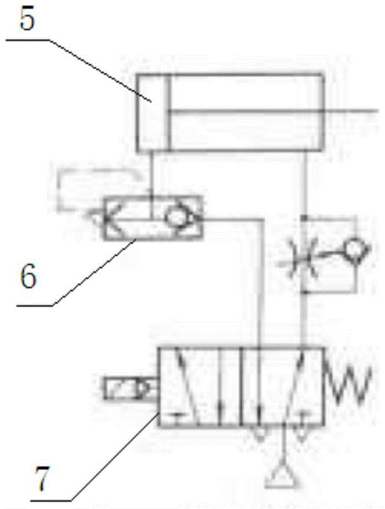
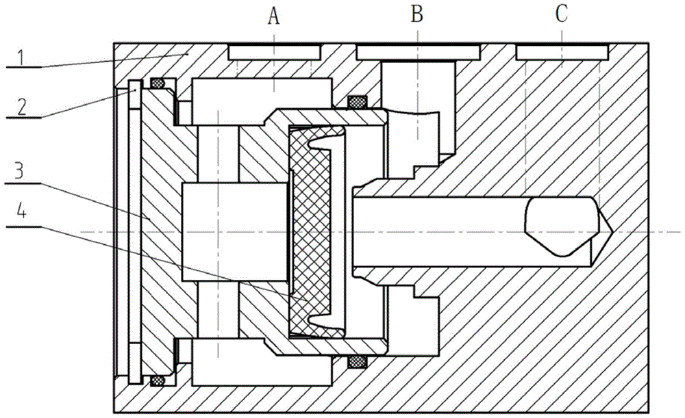
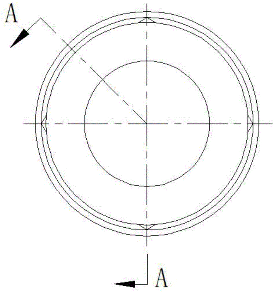
[0026] Such as Figure 2-6 The quick exhaust valve shown includes a valve body and a valve cavity, and a valve core 4 that moves left and right is installed in the valve cavity. The above-mentioned valve body includes a valve seat 1 and a valve core seat 3. The valve seat 1 is provided with a first passage A, a second passage B and a third passage C which are all communicated with the valve cavity. The right end of the above-mentioned valve core seat extends into The valve seat 1 is inserted into the support hole of the valve seat. In order to prevent gas leakage between the first channel A and the second channel B, a sealing ring is added at the support hole. The left end of the valve core seat is inserted into the installation hole on the left end face of the valve seat, and is detachably installed through the annular protrusion on the right side of the installation hole on the valve seat and the retaining ring 2 stuck on the left side of the installation hole. On the valve...


PUM


Abstract

The invention relates to a valve spool and a rapid escape valve applying same and a pneumatic piston actuating mechanism. The valve spool comprises a valve spool body which is frustum-shaped in appearance, the small end of the valve spool body is a bottom end while the large end is provided with a sealed end with a lip, protrusions used for limiting deflection of the valve spool moving in a valve cavity are distributed on the circumferential surface of the valve spool at intervals along the circumferential direction, and the protrusions are located at the areas, close to the bottom end, in the axial direction of the valve spool body and at the areas, within the cylindrical surface where the outer edge of the end surface of the lip is located, in the radial direction of the valve spool body. Since the limit protrusions are circumferentially arranged on the circumferential surface of the valve spool body at intervals, when deformation of the lip is generated from gas pressure and a gap between the valve spool and the inner wall of the valve cavity is enlarged, the valve spool can be centralized under the guiding role of the limit protrusions, and inclination of the valve spool is avoided.

Description

technical field [0001] The invention relates to the technical field of pneumatic components, in particular to a valve core, a quick exhaust valve and a pneumatic piston actuator using the valve core. Background technique [0002] In the automatic pneumatic control system, it is usually required that the pneumatic piston actuator can run smoothly during the action to ensure the safety and reliability of the action. Cycle, improve production efficiency, which requires the addition of a quick exhaust valve in the control system. [0003] Chinese patent document CN2806908Y discloses a quick exhaust valve, the quick exhaust valve includes a valve body and a valve cavity arranged in the valve body, the valve body is provided with an air inlet (i.e. the first passage), an air outlet (i.e. The second channel) and the exhaust port (that is, the third channel), the air inlet, the air outlet and the exhaust port are all connected with the valve chamber, the air inlet is located on one...

Claims


Application Information

Patent Timeline
Patent Type & Authority Patents(China)
IPC IPC(8): F16K1/38F16K11/044F16K27/02F16K31/122
CPCF16K11/044F16K27/02F16K31/122
Inventor 王硕屈利丽牛玉芳王献岭王玉涛刘建辉贾方迪
Owner XINXIANG AVIATION IND GROUP
Learn More