
A gate valve air tightness testing platform

An air-tightness detection and gate valve technology, which is applied in the use of liquid/vacuum for liquid-tightness measurement, and by detecting the appearance of fluid at the leak point, etc. Influence and other problems, to avoid uneven clamping, flexible adjustment, and reliable compression

Active Publication Date: 2017-02-15
WUHU HUAYI VALVE MFG
View PDF5 Cites 0 Cited by
  • Summary
  • Abstract
  • Description
  • Claims
  • Application Information

AI Technical Summary

Problems solved by technology

In order to ensure the airtightness between the valve and the test bench and prevent the gas in the sealing chamber from leaking from between the valve and the test bench, which will affect the test results, the test bench is usually equipped with claws that press the gate valve body. The force of the tight gate valve body is relatively large, and the size of the claws is usually large. When testing a valve with a small diameter, the claws are inconvenient to use, and the contact area between the claws and the valve body is small, and the pressure is large, which is easy It will affect the quality of the valve body, or even crush the valve body

Method used


Image

  • A gate valve air tightness testing platform
  • A gate valve air tightness testing platform
  • A gate valve air tightness testing platform

Examples


Embodiment Construction

[0014] In order to make the technical means, creative features, goals and effects achieved by the present invention easy to understand, the present invention will be further described below in conjunction with specific illustrations.

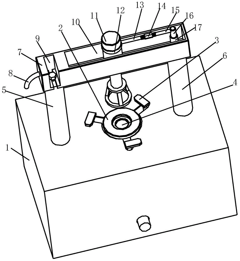
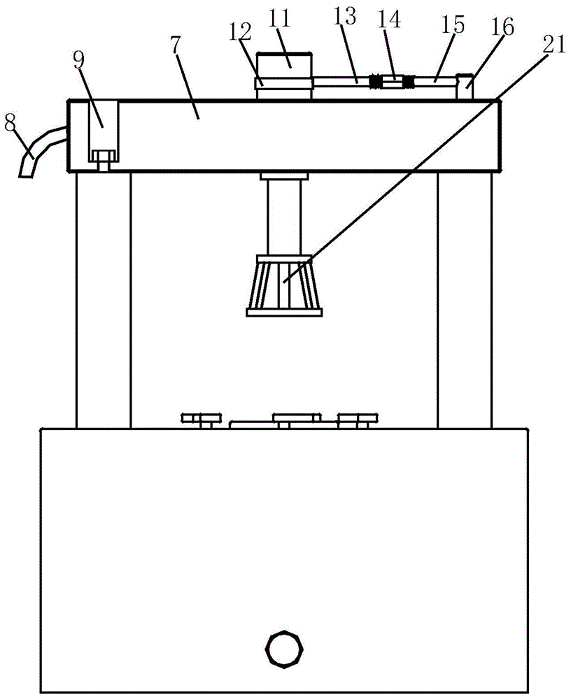
[0015] Such as Figure 1 to Figure 4 As shown, a gate valve air tightness testing platform includes a clamping platform 1, a sealing platform 2 is provided in the middle of the upper end surface of the clamping platform 1, an air supply hole 4 is provided in the center of the sealing platform 2, and the surrounding of the sealing platform 2 is uniform There are claws 3 for fixing and pressing the valve body. The left and right sides of the upper end surface of the clamping platform 1 are respectively provided with a left support column 5 and a right support column 6. A movable clamping column is provided above the clamping platform 1. frame 7, the right part of the upper end surface of the movable compression frame 7 is provided with a groove 10...


PUM


Abstract

The invention relates to an air impermeability detecting table for a sluice valve. The air impermeability detecting table for the sluice valve comprises a clamping table. A sealing table is arranged in the middle of the upper end surface of the clamping table, an air supply hole is formed in the center of the sealing table, and clamping jaws are evenly arranged around the sealing table. A left supporting pillar and a right supporting pillar are correspondingly arranged at the left side and the right side of the upper end surface of the clamping table respectively, a movable compression frame is arranged above the clamping table, a groove is formed in the right portion of the upper end surface of the movable compression frame, a transverse kidney-shaped hole is formed in the middle of the bottom surface of the groove, a round hole is formed in the right portion of the bottom surface of the groove, a notch is formed in the left side of the movable compression frame, a strip-shaped opening is formed in the bottom of the notch, a connector is arranged inside the round hole in a communicating mode, an adapting connection rod is arranged at the upper end of the connector, the adapting connection rod can rotate on the connector, a left threaded rod is fixedly connected to the adapting connection rod, a compression hydraulic cylinder is fixed inside the kidney-shaped hole, and a visible pressing frame is fixed to the lower end of the compression hydraulic cylinder. According to the air impermeability detecting table for the sluice valve, a compression ring is adopted to compress the circumference of a valve body, the condition of uneven clamping generated when the clamping jaws are adopted for clamping is avoided, and the compression hydraulic cylinder can be adjusted on a two-dimensional plane.

Description

technical field [0001] The invention relates to the technical field of detection devices, in particular to a gate valve air tightness detection platform. Background technique [0002] In the valve manufacturing enterprises, the air tightness test must be carried out after the valve is offline. The conventional test method is: first close the valve, and then press a flange of the valve on the test bench. There is an air outlet on the test bench. , when a sealed environment is formed between the valve and the test platform, fill the other side of the valve with water, and open the air outlet on the test platform at the same time, and see if there are bubbles in the water on the other side of the valve to determine the sealing of the valve Is it good. In order to ensure the airtightness between the valve and the test bench and prevent the gas in the sealing chamber from leaking from between the valve and the test bench, which will affect the test results, the test bench is usu...

Claims


Application Information

Patent Timeline
Patent Type & Authority Patents(China)
IPC IPC(8): G01M3/08
Inventor 冯俊德季昌城
Owner WUHU HUAYI VALVE MFG
Learn More