
Liquid floated gyroscope

A liquid floating gyroscope, integrated technology, applied in the direction of rotating gyroscope, etc., can solve the problems of low reliability, troublesome ground storage and testing, accelerated gas seal leakage, etc., so as to improve reliability, avoid gas leakage, and improve gas leakage. The effect of sealing performance

Inactive Publication Date: 2013-01-23
SHANGHAI XINYUE METER FACTORY
View PDF3 Cites 1 Cited by
  • Summary
  • Abstract
  • Description
  • Claims
  • Application Information

AI Technical Summary

Problems solved by technology

With this kind of secondary sealing structure that makes the gyro back cover have about 1 atmosphere of pressure, the reliability is not high
Especially when the ground high and low temperature test and thermal vacuum test will accelerate the leakage of the air seal, causing greater trouble to the ground storage and test

Method used


Image

  • Liquid floated gyroscope

Examples


Embodiment Construction

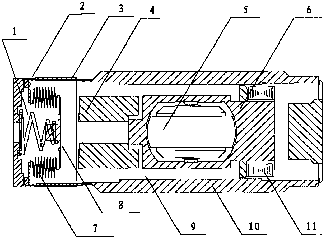
[0016] Such as figure 1 Shown is a schematic structural view of the liquid floating gyroscope of the present invention. The liquid floating gyroscope includes a conical spring 1, a rear cover 2, a rear cover 3, a torque device 4, a motor 5, a buoy 6, a bellows 7, a gasket 8, a floating liquid 9, a housing 10, and a sensor 11. Wherein the bellows 7 and the gasket 8 are welded into one body, a back cover 2 is installed on the outer diameter of the back cover 3 of the housing, and the back cover 2 and the back cover 3 are bonded with glue E-16; the bottom of the inner hole of the back cover 2 There is a groove in the upper processing, and the back cover 2 is made of the same material as the back cover 3, all selecting expansion alloy 4J34 steel for use.

[0017] The large end of the conical spring 1 is placed in the groove at the bottom of the inner hole of the back cover 2 , and the small end is placed on the boss of the gasket 8 . The total number of turns of the conical spri...


PUM


Abstract

The invention discloses a liquid floated gyroscope which comprises a shell, a rear shade, a corrugated pipe and a gasket, wherein the corrugated pipe and the gasket are fixedly connected into a whole. The liquid floated gyroscope is characterized in that the rear shade of the shell is externally provided with a rear cover, and the rear cover is glued with the rear shade; and the big end of a conical spring is sleeved in the rear cover, and the small end of the conical spring is sleeved on the gasket. Compared with the prior art, the liquid floated gyroscope provided by the invention has the advantages and beneficial effects that the conical spring is adopted, the small rigidity problem of the existing corrugated pipe is overcome, the rigidity is improved, the rear cover is glued with the rear shade, the occurrence of a gas leakage phenomenon is avoided, and the hermetic seal property of the gyroscope is improved.

Description

technical field [0001] The invention relates to a liquid floating rate gyroscope, in particular adopting a spring to increase the inner cavity pressure of the liquid floating gyroscope so as to reduce the influence of the pressure difference in the vacuum environment of the liquid floating gyroscope. Background technique [0002] The liquid buoyancy rate gyroscope is the core device of the satellite gyro combination, which includes a shell, a rear cover, a torquer, a sensor, a motor, a buoy, a bellows, a gasket, and a floating liquid, and has the characteristics of low power consumption and small size. However, the thin wall thickness of the existing bellows is only 0.1mm, the volume is small, the rigidity is small, and the pressure is insufficient, resulting in a huge pressure difference defect inside and outside the gyroscope. Especially under vacuum conditions, besides the floating liquid, air bubbles or cavities appear in the inner cavity of the gyroscope. reach a new b...

Claims


Application Information

Patent Timeline
Patent Type & Authority Applications(China)
IPC IPC(8): G01C19/04
Inventor 李剑文张明举吴建铭邵添羿
Owner SHANGHAI XINYUE METER FACTORY
Learn More