Fingerprint detection circuit, capacitance type finger sensor comprising same, and mobile terminal

A fingerprint detection and capacitive technology, applied in the field of identification, can solve the problems of VIN_1 whose amplitude cannot follow the possible dynamic changes, high-precision signal source indicators, high cost and power consumption, etc., to achieve small chip area occupied, The circuit structure is simple and the effect of improving the accuracy of fingerprint recognition

Active Publication Date: 2015-01-07
SHENZHEN GOODIX TECH CO LTD
View PDF4 Cites 20 Cited by
  • Summary
  • Abstract
  • Description
  • Claims
  • Application Information

AI Technical Summary

Problems solved by technology

The problem with this method is that, first of all, the amplitude of the output VCAN of the high-precision signal source cannot follow the VIN_1 that may change dynamically (this is because VIN_1~VIN_n is determined by the coupling capacitance between the finger and the fingerprint detection unit, and this capacitance may be dynamically changed. change), so the signal amplitude of VPXL_1 may still contain a considerable part of the base signal amplitude, and the final output signal VOUT_1 after the amplifier is the same
Secondly, assuming that VIN_1 is fixed, in order to obtain the ideal basal elimination effect, the requirements for the high-precision signal source are very high, and implementing the corresponding signal source inside the chip will consume more cost and power consumption

Method used


Image

  • Fingerprint detection circuit, capacitance type finger sensor comprising same, and mobile terminal
  • Fingerprint detection circuit, capacitance type finger sensor comprising same, and mobile terminal
  • Fingerprint detection circuit, capacitance type finger sensor comprising same, and mobile terminal

Examples


Embodiment Construction

[0025] It should be understood that the specific embodiments described here are only used to explain the present invention, not to limit the present invention.

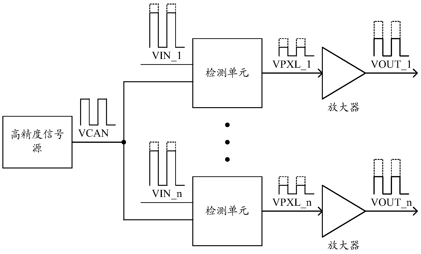
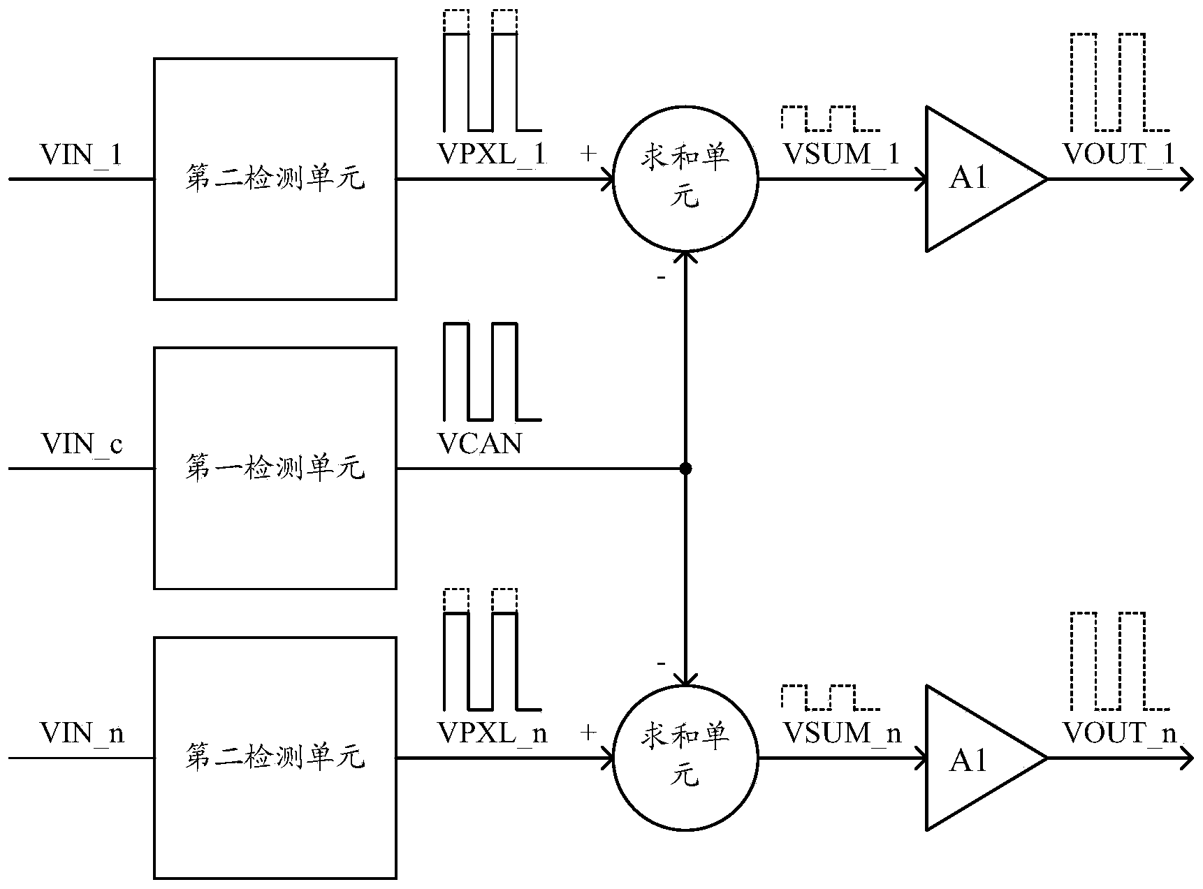
[0026] In the embodiment of the present invention, the capacitive fingerprint sensor includes a fingerprint detection panel, which is located in a fingerprint detection area on the fingerprint detection panel, and a fingerprint detection circuit is arranged in the fingerprint detection area, such as figure 2 as shown, figure 2 It is a schematic diagram of a fingerprint detection circuit proposed by the present invention, and the fingerprint detection circuit includes a plurality of detection units arranged in an array, a summation unit, and a first amplifier A1. Such as image 3 As shown, in this embodiment, one of the multiple detection units is arbitrarily selected (of course, more than one can be selected) as the first detection unit, and the remaining detection units are used as the second detection unit. The f...


PUM


Abstract

The invention discloses a fingerprint detection circuit which comprises a plurality of detection units arranged in an array. The fingerprint detection circuit is characterized in that summation units are further included, each detection unit comprises a first detection unit and a second detection unit, the first detection units and the second detection units are connected with the summation units, and the summation units carry out summation on output signals of the second detection units and output signals of the first detection units to eliminate substrate signals in the output signals of the second detection units and obtain useful signals comprising fingerprint information. According to the fingerprint detection circuit, at least one detection unit is selected as a neutralizing unit, and the output signals of other detection units and the output signals of the detection unit which is used as the neutralizing unit are subjected to summation to eliminate the substrate signals in the output signals of the detection units and obtain the useful signals comprising the fingerprint information. Compared with the prior art, the eliminating capacity of the substrate signals is improved, and fingerprint identification precision is further improved.

Description

technical field [0001] The invention relates to the technical field of identification, in particular to a fingerprint detection circuit, a capacitive fingerprint sensor, and a mobile terminal. Background technique [0002] With the progress of society and the development of technology, in recent years, e-commerce services such as mobile banking, mobile wallet, and online shopping have been widely used on smart mobile devices. In contrast, the public has higher and higher requirements for the performance of integrated electronic components and network information security. Fingerprints are an effective means of personal identification due to their uniqueness and stability. There are many types of fingerprint sensors, and there are currently three mainstream types: optical fingerprint sensors, crystal capacitive (or pressure-sensitive) fingerprint sensors, and ultrasonic fingerprint sensors. Optical equipment captures images using the principle of total reflection and uses C...

Claims


Application Information

Patent Timeline
Patent Type & Authority Applications(China)
IPC IPC(8): G06K9/00G06F3/044
CPCG06V40/1306H03K17/962H04M2203/6054
Inventor 詹昶
Owner SHENZHEN GOODIX TECH CO LTD
Why Eureka
Try Eureka