Non-contact power transmission system

A power transmission, non-contact technology, applied in electromagnetic wave systems, circuits, inductors, etc., can solve the problems of difficult application, short transmission distance, large outer diameter of the magnetic core, etc., to reduce the requirements, meet the transmission distance, and meet the requirements Effect

Inactive Publication Date: 2015-01-07
CHINA AVIATION OPTICAL-ELECTRICAL TECH CO LTD
View PDF4 Cites 3 Cited by
  • Summary
  • Abstract
  • Description
  • Claims
  • Application Information

AI Technical Summary

Problems solved by technology

For non-contact power transmission systems, the outer diameter of the flat magnetic core is too large to be used; while the transmission distance of the magnetic core with other structures is too short

Method used


Image

  • Non-contact power transmission system
  • Non-contact power transmission system
  • Non-contact power transmission system

Examples


Embodiment Construction

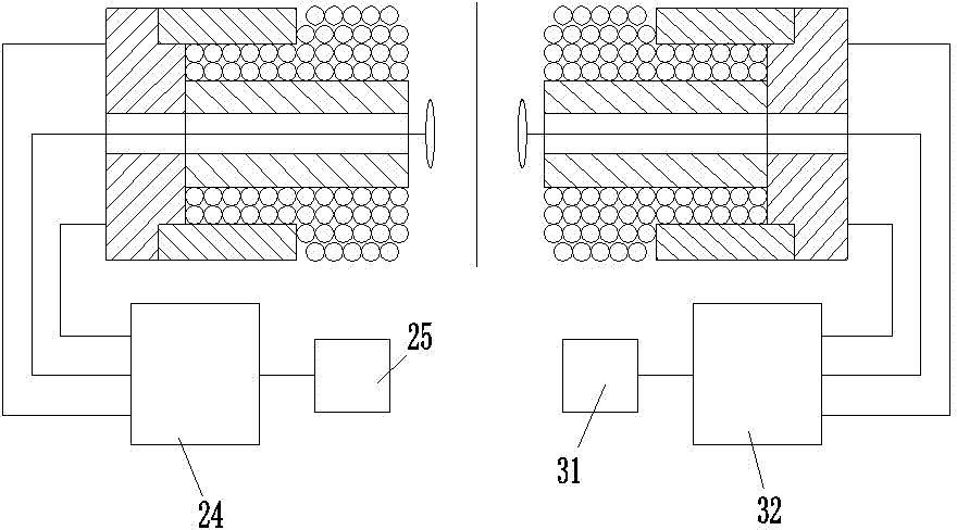
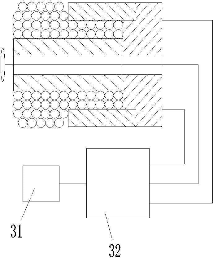
[0020] Examples of magnetic cores for contactless power transfer systems, such as Figure 1-8 As shown, the contactless power transmission system includes a transmitting end and a receiving end.

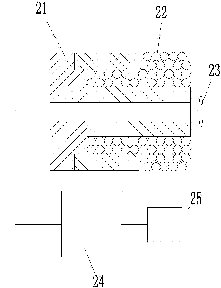
[0021] The transmitting end includes a magnetic core 21 , a power coil 22 , a signal antenna 23 , a transmitting control module 24 and a power supply and signal receiving processor 25 . The magnetic core 21 includes an inner ring 11 , an outer ring 12 and a base 13 disposed at one end of the inner ring and the outer ring.

[0022] In this embodiment, both the inner ring and the outer ring are circular sleeves and each has an integrated structure, wherein the inner ring 11 and the outer ring 12 are coaxially located in the outer ring 12, and the inner hole of the inner ring 11 is axially penetrated. , which are used for the corresponding cables to pass through.

[0023] Both the inner and outer rings are fixed on the base 13, and the base 13 is provided with a through hole correspon...


PUM


Abstract

The invention relates to the field of electrical connectors, in particular to a non-contact power transmission system. The non-contact power transmission system comprises a transmitting end and a receiving end, wherein each of the transmitting end and the receiving end comprises a magnetic core and a coil; each magnetic core comprises an inner ring, an outer ring and a base; the inner ring and the outer ring are fixed on the base through corresponding ends respectively; the coil is wound on the inner ring; one end, away from the base, of the inner ring protrudes out of the corresponding end of the outer ring. According to the non-contact power transmission system, one end, away from the base, of each of the inner rings of the magnetic cores of each of the transmitting end and the receiving end protrudes out of the corresponding ends of the outer rings. Therefore, the electromagnetic field can be better guided to be distributed in a wider range, so that the non-contact power transmission system has a longer power transmission distance and a wider range, thereby reducing the requirements on the shape of the magnetic core. In conclusion, the non-contact power transmission system is not only consistent with the size of non-contact power transmission systems, but also to meets the requirements on transmission distance.

Description

technical field [0001] The invention relates to the field of electrical connectors, in particular to a non-contact power transmission system. Background technique [0002] Non-contact power transmission technology is a new technology in the ascendant. Its mechanism of action involves transmitting an alternating electromagnetic field from coil to coil, and induces alternating current in the receiving coil, and supplies it to portable electrical devices such as batteries and mobile phones. The main difficulty of this technology is: how to increase the distance of non-contact power transmission while ensuring the transmission efficiency. [0003] As we all know, adding a magnetic core to the coil can significantly increase the inductance of the coil, so that the same inductance value can be achieved with fewer coil turns, and the reduction in the number of coil turns will reduce the resistance loss of the wire. The magnetic core can also reshape the distribution of the electr...

Claims


Application Information

Patent Timeline
Patent Type & Authority Applications(China)
IPC IPC(8): H02J17/00H01F38/14H02J50/10H02J50/80
CPCH01F38/14
Inventor 王颖辉张晓光李强
Owner CHINA AVIATION OPTICAL-ELECTRICAL TECH CO LTD
Why Eureka
Try Eureka