Joining components by means of resistance welding

A technology of resistance welding and components, which is applied in the direction of resistance welding equipment, welding equipment, resistance electrode holders, etc., and can solve the problems of the necessity of multiple welding stations in a large takt time

Active Publication Date: 2015-01-07
VOLKSWAGEN AG
View PDF17 Cites 4 Cited by
  • Summary
  • Abstract
  • Description
  • Claims
  • Application Information

AI Technical Summary

Problems solved by technology

In large components with long welding spot rows, this leads to relatively large cycle times and / or the necessity of several welding stations

Method used


Image

  • Joining components by means of resistance welding
  • Joining components by means of resistance welding
  • Joining components by means of resistance welding

Examples


Embodiment Construction

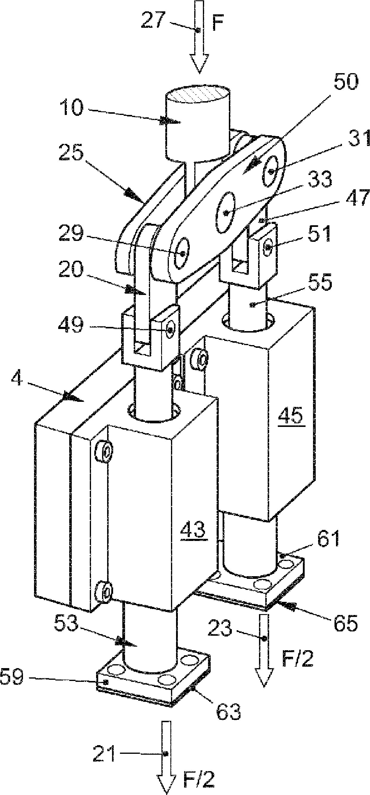
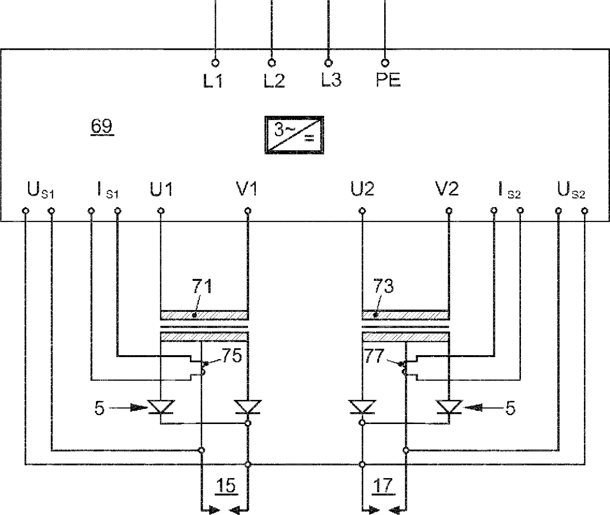
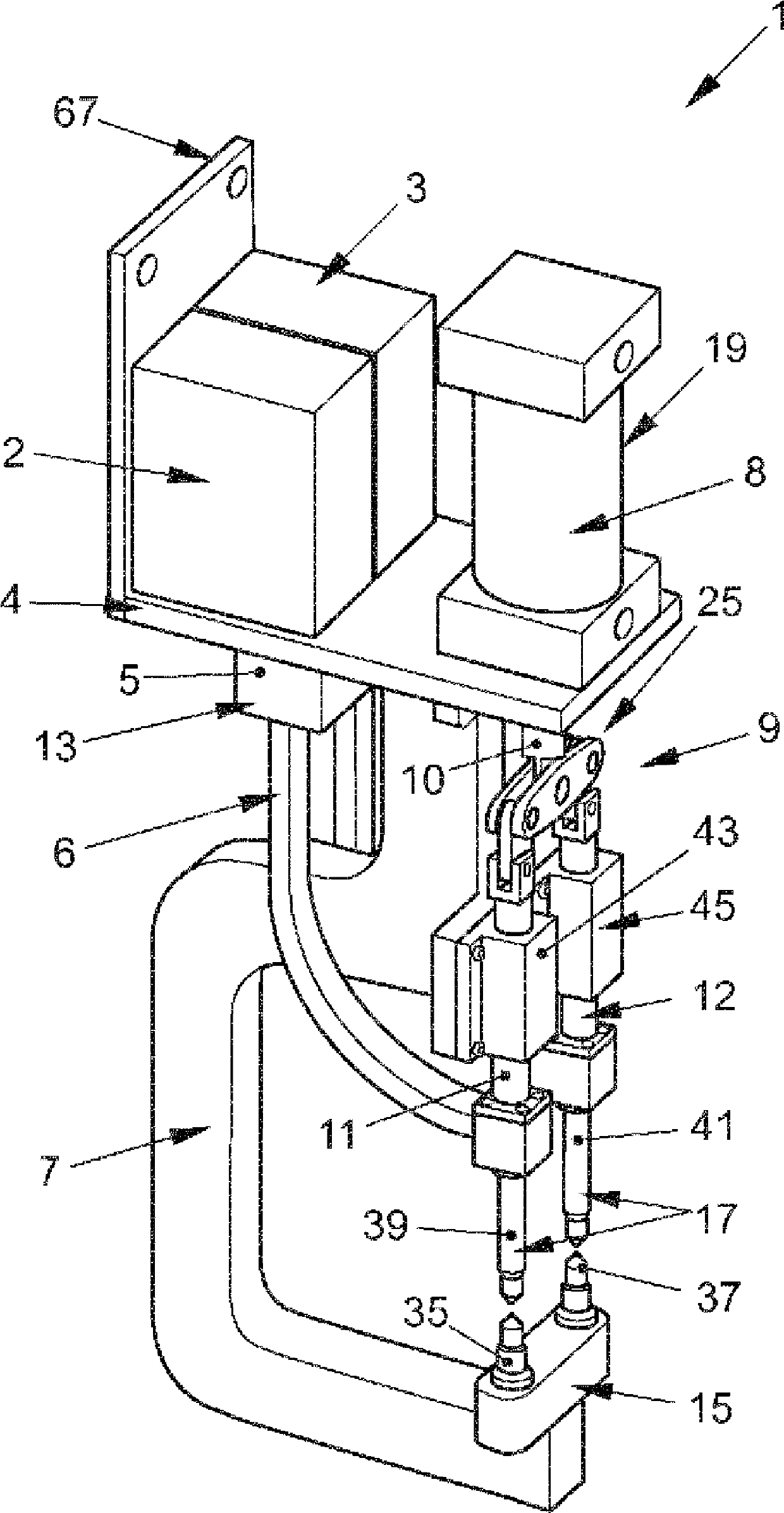
[0025] figure 1 A three-dimensional view of the C-Bügel (C-Bügel) 7 of the welding device 1 is shown diagonally from the front and above. The welding device 1 has an electrode pair 15 and another electrode pair 17. Two or more mating partners may be positioned between the electrode pairs 15, 17. The total electrode force 27 is applied to the electrode pairs 15 and 17 by means of the force source 19. In this way, the joining partner is temporarily fixed between the electrode pairs 15, 17 and pressed together so that the two welding currents provided by the welding transformer (Schweisstransformator) 2 and the other welding transformer 3 at least partially melt the material of the joining partner And as a result, the joint counterparts are connected at the two joint locations by means of resistance welding.

[0026] The welding transformers 2 and 3 are connected to the moving welding electrodes 39, 41 of the welding electrode pair 15, 17 by means of a secondary cable (Sekundaerst...


PUM


Abstract

A welding device (1) for joining components by means of resistance welding is proposed, comprising: - a pair of electrodes (15), by means of which an electrode force (21) and an electrical welding current IS1 can be introduced into the components, - at least one further pair of electrodes (17), by means of which an electrode force (23) and a further electrical welding current IS2 can be introduced into the components, - a power source (19), by means of which the electrode forces (21, 23) can be generated, - a coupling link (35), which is mechanically connected between the power source (19) and the pairs of electrodes (15, 17) and by means of which a total electrode force (27) that can be generated by the power source (19) can be divided into the electrode force (21) and the further electrode force (23).

Description

Technical field [0001] The invention relates to a welding device for joining components by means of resistance welding and a method that can be performed by means of the welding device. Background technique [0002] Due to the pursuit of automation, resistance welding is a joining method often encountered in car body manufacturing. Robotic welding tongs (Roboterschweisszange) are known, which produce solder joints for the starting position (Anfahr position) and the working cycle. In large components with long rows of welding points, this leads to a relatively long cycle time and / or the necessity of multiple welding stations. In order to increase productivity, it is known to use welding tongs, and two welding points can be introduced into each starting position and working cycle. The document DE 10 2006 005 920 A1 describes a resistance welding method for welding three components. The components must be implemented as hollow profiles. The welding current is introduced by two e...

Claims


Application Information

Patent Timeline
Patent Type & Authority Applications(China)
IPC IPC(8): B23K11/11B23K11/31
CPCB23K11/312B23K11/115B23K11/315B23K11/318B23K11/317
Inventor A.福伊格特M.格劳尔
Owner VOLKSWAGEN AG
Why Eureka
Try Eureka