High-pressure large-diameter well piping system

A technology of pipeline system and pipeline wall, applied in the field of well pipeline system, can solve problems such as increasing groundwater formation, and achieve the effect of remarkable efficiency

Active Publication Date: 2018-02-02
布鲁斯 A 通盖特
View PDF45 Cites 0 Cited by
  • Summary
  • Abstract
  • Description
  • Claims
  • Application Information

AI Technical Summary

Problems solved by technology

[0063] There is a need for increased recovery of fluids within subterranean deposits and the use of fewer main boreholes penetrating through the groundwater formation, which cannot be achieved by utilizing conventional single concentric bore well designs due to the increased recovery rate Typically requires additional wells or penetration through groundwater formations and cap rocks containing toxic fluids, thereby increasing the risk of leakage into said groundwater formations

Method used


Image

  • High-pressure large-diameter well piping system
  • High-pressure large-diameter well piping system
  • High-pressure large-diameter well piping system

Examples


Embodiment Construction

[0136] Before describing in detail selected embodiments of the invention, it is to be understood that the invention is not limited to the specific embodiments described herein, but that the invention can be practiced or carried out in various ways.

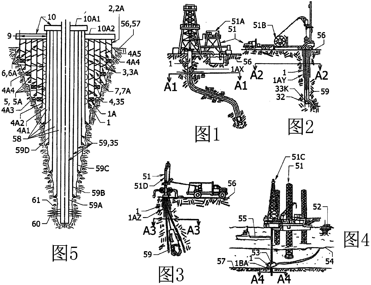
[0137] now refer to figure 1 , 2 . The arrangement of the prior art coiled pipe drilling (51B) rig (51), the wireline drilling (51D) rig (51) above the line A3-A3 and the prior art offshore drilling above the line A4-A4 Schematic illustration of a cross-sectional portion of a spud drilling (51C) drill frame (51) through the environment and subterranean formations. About attached Figure 1-4 , any drilling frame including the described drilling frame (51) can be used to operate and / or drill within the large diameter high pressure piping system (1); however, the larger lifting capacity drilling frames (51A and 51C) It is generally preferred for installing said piping system (1), especially when these drill stands are suitable f...


PUM


Abstract

Well conduit system and methods using a first outer conduit wall and at least one second inner conduit wall positioned through a wellhead to define an annulus with radial loading surfaces extending across the annulus and radially between at least two of the conduit walls to form passageways through subterranean strata concentrically, wherein an inner pipe body of greater outer diameter is inserted into an outer pipe body of lesser inner diameter by elastically expanding the circumference of the outer pipe body and elastically compressing the circumference of the inner pipe body, using a hoop force exerted therebetween. Releasing the hoop force after insertion will release the elastic expansion and compression of the pipe bodies to abut the radial loading surfaces within the annulus for sharing elastic hoop stress resistance and thereby forming a greater effective wall thickness, capable of containing higher pressures than the conduit walls could otherwise bear.

Description

[0001] Cross References to Related Applications [0002] This application is a Patent Cooperation Treaty (PCT) application claiming priority to UK Patent Application No. GB1203649.7, filed 1 March 2012, entitled "High Pressure Large Bore Well Conduit System" right; the UK patent application number GB1203649.7 claims the following priority: filed on March 1, 2011 and published on September 29, 2011 under the title of WO2011 / 119198A1 entitled "Manifold String For Selectively Controlling Flowing Fluid Streams of Varying Velocities PCT Application No. US2011 / 000377 for "In Wells From A Single Main Bore" (Manifold String for Selectively Variable Speed ​​Control of Flow Flow from a Single Main Bore in a Well); filed March 15, 2011 and filed in 2011 British Patent Application No. 1104278.5 of the same title published as GB2479432A on 12 October 2011; filed on 1 March 2011 and published as WO2011 / 119197A1 on 29 September 2011 as "Pressure Controlled Well Construction and PCT Applicati...

Claims


Application Information

Patent Timeline
Patent Type & Authority Patents(China)
IPC IPC(8): E21B7/00F16L1/00
CPCE21B17/18E21B23/12E21B41/0035E21B43/14E21B17/00E21B33/047E21B43/10E21B2200/01
Inventor 布鲁斯·A.·通盖特
Owner 布鲁斯 A 通盖特
Why Eureka
Try Eureka