Rod penetrating type lifting scaffold

A technology for lifting scaffolding and piercing rods, which is applied in the direction of scaffolding for building structure support, building structure support, building structure support, etc., can solve the problems of large manpower consumption, high cost, and large investment at one time, and achieve less consumption of steel pipes, The effect of saving electricity resources and saving investment

Inactive Publication Date: 2015-01-14
王汉猷 +1
View PDF4 Cites 3 Cited by
  • Summary
  • Abstract
  • Description
  • Claims
  • Application Information

AI Technical Summary

Problems solved by technology

[0002] At present, the scaffolds used in the construction of high-rise buildings include floor-standing, section steel cantilevered, and fully automatic attachment. Among them, the floor-to-ceiling scaffold consumes a lot of steel pipes and a lot of labor. When the number of floors of the building is less than 10 floors, a single pole can be used. , when it is more than 10 floors, double poles must be used, otherwise the safety is not enough, a large amount of steel must be prepared for the section steel cantilevered scaffolding, and the one-time investment is relatively large. The attached integral fully automatic scaffold has strict requirements and must be contracted by a specialized company Expensive, there is no scaffolding that can solve the above problems at the same time

Method used


Image

  • Rod penetrating type lifting scaffold
  • Rod penetrating type lifting scaffold
  • Rod penetrating type lifting scaffold

Examples


Embodiment Construction

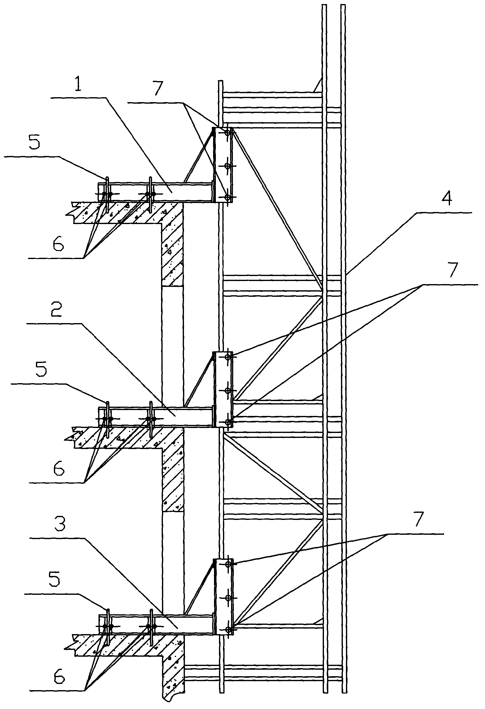
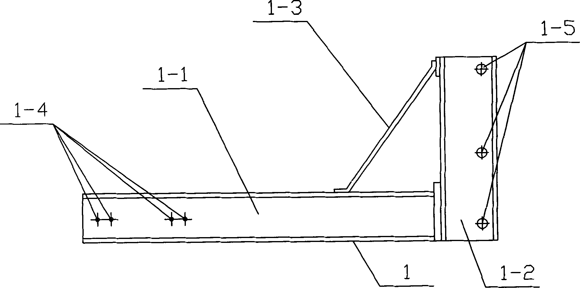
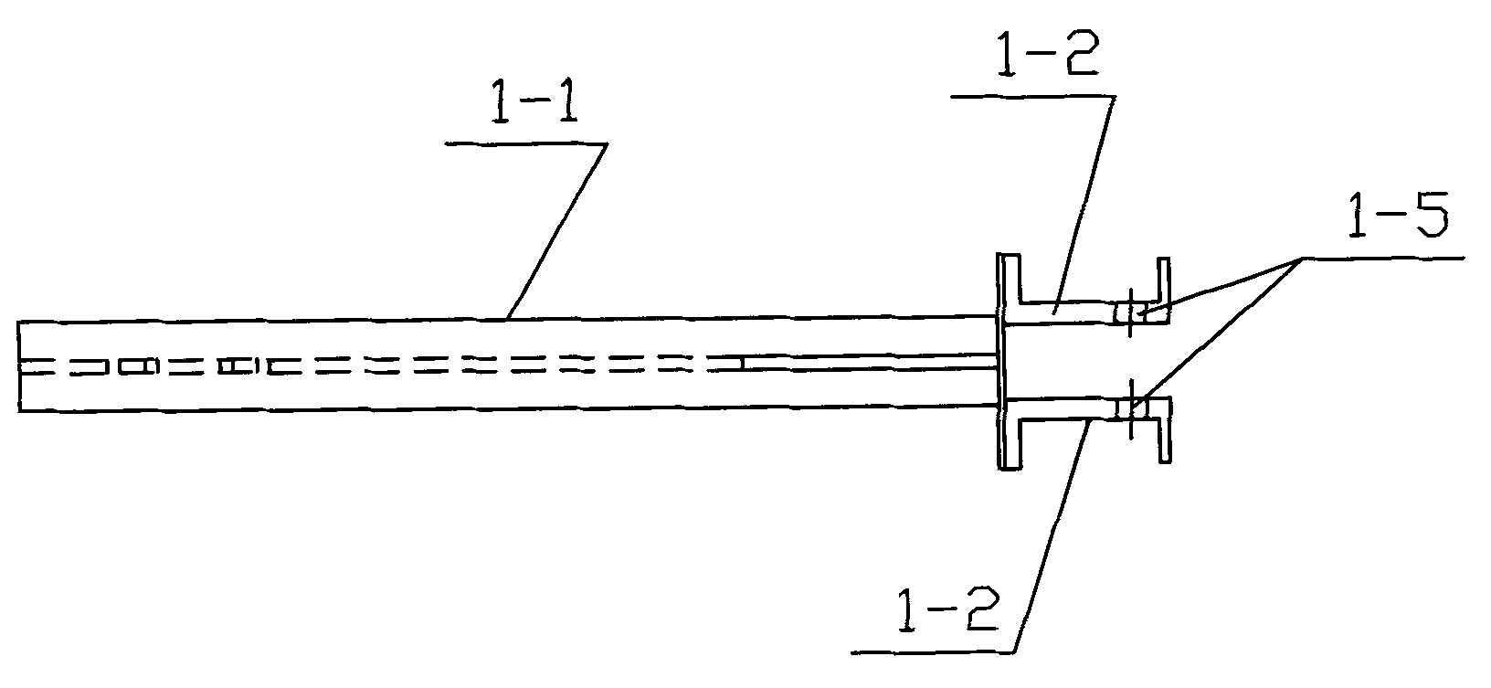
[0029] see Figure 1-12 , the specific embodiment adopts the following technical scheme: it comprises the first track 1, the second track 2, the third track 3 and the bearing frame 4; the structures of the first track 1, the second track 2 and the third track 3 are the same, and the A track 1 includes I-beam 1-1, channel steel 1-2, reinforcing rib 1-3, fixing hole 1-4 and limit fixing hole 1-5, and I-beam 1-1 is perpendicular to channel steel 1-2 set, and one end of the I-beam 1-1 is welded on one side of the channel steel 1-2, a reinforcing rib 1-3 is arranged between the I-beam 1-1 and the channel steel 1-2, and the I-beam 1-1 Two sets of fixing holes 1-4 are arranged horizontally on the upper side, and several limit fixing holes 1-5 are vertically arranged on the channel steel 1-2, and the first track 1, the second track 2 and the third track 3 pass through the I-beam 1 -1 is inserted into the inside of the pre-embedded U-shaped part 5, and the pre-embedded U-shaped part 5...


PUM


Abstract

The invention discloses a rod penetrating type lifting scaffold, and relates to the technical field of architectural engineering construction. H-shaped steel (1-1) and channel steel (1-2) are perpendicularly arranged, a reinforcing rib (1-3) is arranged between the H-shaped steel (1-1) and the channel steel (1-2), and a hard wooden wedge (9) is arranged at the upper gap of the H-shaped steel (1-1) and an embedded U-shaped piece (5). Reinforcing plates (4-5) are arranged between cross bars (4-4), an inner vertical rod (4-1) penetrates into a hole of the channel steel (1-2), and dowels (7) are inserted into limiting fixing holes (1-5) to be fixed. Each dowel (7) is provided with two location holes (7-1), location pins (8) are arranged in the two location holes (7-1) respectively, and the inner vertical rod (4-1) is arranged between the two location holes (7-1). The number of consumed steel tubes is small, the investment is saved, the cost is lowered, the lifting scaffold not only can be used for body construction but also can be used for decoration construction, electricity resources are saved, and convenience and practicability are achieved.

Description

Technical field: [0001] The invention relates to the technical field of construction engineering, in particular to a rod-through lifting scaffold. Background technique: [0002] At present, the scaffolding used in the construction of high-rise buildings includes floor-standing, section steel cantilevered, and fully automatic attachment. Among them, the floor-to-ceiling scaffold consumes a lot of steel pipes and a lot of labor. When the number of floors of the building is less than 10 floors, a single pole can be used. , when it is more than 10 floors, double poles must be used, otherwise the safety is not enough. The section steel cantilever scaffold must have a large amount of section steel, which requires a large investment at one time. The attached integral fully automatic scaffold has strict requirements and must be contracted by a specialized company. Expenses are expensive, and there is no scaffolding that can solve the above problems at the same time. [0003] Backgr...

Claims


Application Information

Patent Timeline
Patent Type & Authority Applications(China)
IPC IPC(8): E04G3/28
Inventor 王汉猷王安华储晓雷徐玉健
Owner 王汉猷
Why Eureka
Try Eureka