
Backlight source and display device

A backlight and light source technology, applied in the display field, can solve the problems affecting the display quality of the display panel, the firefly Hotspot phenomenon, etc., and achieve the effect of improving the display quality, avoiding uneven brightness and darkness, and uniform light.

Inactive Publication Date: 2015-01-14
HEFEI XINSHENG OPTOELECTRONICS TECH CO LTD +1
View PDF8 Cites 4 Cited by
  • Summary
  • Abstract
  • Description
  • Claims
  • Application Information

AI Technical Summary

Problems solved by technology

[0004] like figure 1 As shown, since the light irradiation range of each LED lamp 4 is a fan-shaped area, and the included angle of the fan-shaped area is usually 120°, the light brightness in the fan-shaped area is relatively high, so the fan-shaped area forms the entire LED lamp. The bright light area 5 of the bar, and the light brightness in the interval area between the two LED lamps 4 that are spaced apart from each other is relatively low, so it is easy to form a dark area 6 in the interval area between the two LED lamps 4, resulting in the entire The light emitted by the LED light bar has a firefly Hotspot phenomenon (that is, areas with high brightness and areas with low brightness alternate with each other, causing multiple points of light and dark to appear on the display panel), which seriously affects the display quality of the display panel.

Method used


Image

  • Backlight source and display device
  • Backlight source and display device

Examples


Embodiment 1

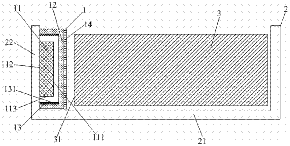
[0023] This embodiment provides a backlight, such as figure 2 As shown, it includes a light source 1, a backplane 2 and a light guide plate 3, the backplane 2 includes a bottom plate 21 and a frame 22 surrounding the edge of the bottom plate 21, the light guide plate 3 is arranged above the bottom plate 21, the light source 1 is arranged on the frame 22, and The light source 1 is opposite to the edge end surface 31 of the light guide plate 3 . The light source 1 includes a light emitting unit 11 . The light source 1 also includes a lampshade 12 wrapped outside the light emitting unit 11 .

[0024] Wherein, the lampshade 12 is made of a mixed material of transparent plastic and PMMA or transparent PC particles, and the PMMA or transparent PC particles are evenly mixed with the transparent plastic. It should be noted that the transparent plastic is an ordinary light-transmitting plastic different from the performance of PMMA or transparent PC particles, such as the melting poin...

Embodiment 2

[0034] This embodiment provides a display device, including the backlight source in Embodiment 1.

[0035] By adopting the backlight source in Embodiment 1, not only the backlight effect of the display device is improved, but also the display quality of the display device is improved.

[0036] The display device provided by the present invention may be any product or component with a display function such as a liquid crystal panel, a liquid crystal TV, a monitor, a mobile phone, a navigator, and the like.


PUM


Abstract

The invention provides a backlight source and a display device. The backlight source comprises a light source, a back plate and a light guide plate, wherein the back plate comprises a bottom plate and a side frame arranged on the edge of the bottom plate in a surrounding way, the light guide plate is arranged above the bottom plate, the light source is arranged on the side frame, in addition, the light source is opposite to the edge end surface of the light guide plate, the light source comprises an illumination unit and a lamp shade arranged outside the illumination unit in a covering way, and light rays given out from the illumination unit can be uniform through the lamp shade. The backlight source has the advantages that the lamp shade is arranged outside the illumination unit in the covering way, and the lamp shade can realize the uniformization treatment on the light rays given out by the illumination unit, so that the light rays given out by the illumination unit can become more uniform, the nonuniform brightness phenomenon (i.e., the Hotspot firefly phenomenon) of the light rays given out by the illumination unit can be avoided, and further, the backlight effect of the backlight source is improved.

Description

technical field [0001] The present invention relates to the field of display technology, in particular to a backlight source and a display device. Background technique [0002] A liquid crystal display (LCD: Liquid Crystal Display) has become a mainstream product among flat panel display devices due to its small size, low power consumption, and no radiation. The backlight source is an essential device in the liquid crystal display device, and the backlight source is used to provide backlight for the display panel when displaying. [0003] In order to adapt to the development of thinner and lighter display panels, the backlight source usually adopts a side-input type. In the side-lit backlight, the light source is usually arranged on one edge of the light guide plate, so that the light emitted by the light source is incident into the light guide plate from the edge end surface of the light guide plate. The light source in the backlight usually adopts an LED light bar, and a...

Claims


Application Information

Patent Timeline
Patent Type & Authority Applications(China)
IPC IPC(8): F21S8/00F21V3/04F21V13/00F21Y101/02
CPCG02F1/133615
Inventor 许海峰尹傛俊涂志中辛武根黄建明王旭东
Owner HEFEI XINSHENG OPTOELECTRONICS TECH CO LTD
Learn More