
An optical microscopic stress measurement device based on the principle of aperture deformation

An optical microscope and measuring device technology, which is applied to measuring devices, using optical devices, and measuring the force of change in optical properties of materials when they are under stress, can solve the problem of difficulty in achieving breakthroughs in kilometer test depths and hindering applications. , The stress relief method is complicated in the testing process, and it achieves significant scientific significance and economic and practical value, the requirements of the test environment are reduced, and the reliability and application range are improved.

Active Publication Date: 2017-05-10
INST OF ROCK & SOIL MECHANICS CHINESE ACAD OF SCI
View PDF7 Cites 0 Cited by
  • Summary
  • Abstract
  • Description
  • Claims
  • Application Information

AI Technical Summary

Problems solved by technology

Usually, this kind of test device works well when measuring in shallow holes, but as the test depth increases, the temperature and groundwater conditions will change, and it is difficult for the commonly used sensors to meet the requirements, making the test depth of this test device Often limited to a range of several hundred meters, it is difficult to achieve a breakthrough in the test depth of a thousand meters
In addition, the equipment installation and testing process of the stress relief method is relatively complicated, including multiple steps such as measuring hole drilling, sensor layout, and release hole drilling and real-time measurement. Each step requires the cooperation and separation of the drilling machine, especially the sensor layout The problem of lead wires seriously hinders the application of this method in deep holes

Method used


Image

  • An optical microscopic stress measurement device based on the principle of aperture deformation
  • An optical microscopic stress measurement device based on the principle of aperture deformation
  • An optical microscopic stress measurement device based on the principle of aperture deformation

Examples


Embodiment Construction

[0045] Below in conjunction with accompanying drawing and implementation example the present invention is further described:

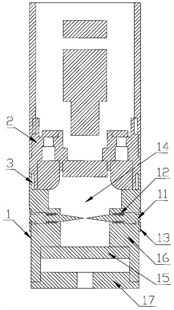
[0046] like Figure 1~4 As shown, an optical microscopic stress measurement device based on the principle of aperture deformation includes a multi-stylus measurement component 1 and an optical microscopic imaging component 2 . The multi-stylus measuring component 1 and the optical microscopic imaging component 2 are connected into one body through a threaded button 3 .

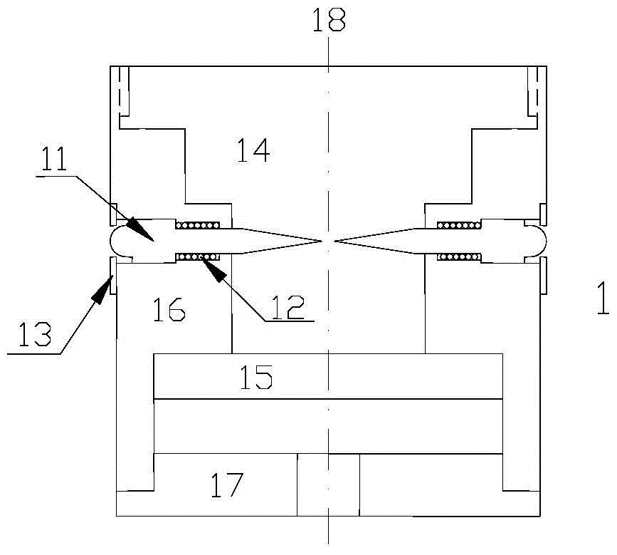
[0047] The multi-probe measurement component 1 includes a stylus 11 , a spring 12 , a limit card 13 , a balance weight 15 , a housing 16 and a bottom cover 17 . The contact pins 11 are in pairs, and the number is not less than three pairs; the contact pins 11 are symmetrically arranged and located on the same cross-section in the housing 16;

[0048] The stylus 11 includes a contact 111, a stylus 113, a stylus spring rod 114 and a stylus tip 112 connected in sequence, the stylus 111 ...


PUM


Abstract

The invention discloses an optical microscope geostress measurement device based on the aperture deformation principle. The optical microscope geostress measurement device comprises a multi-contact-probe measurement component and an optical microscope imaging component; a plurality of sets of contact probes are installed in the multi-contact-probe measurement component in a paired mode, a contact of each contact probe is in contact with the hole wall of a drilled hole to sense aperture changes, and probe tips of the contact probes are concentrated in a tiny area to be synchronous with the contacts in change. The optical microscope imaging component is a sealing barrel with a window and a light source window, and a camera, a microscope lens, a digital compass and an annular light source are located in the optical microscope imaging component. The multi-contact-probe measurement component and the optical microscope imaging component are connected together through a screw; in addition, the microscope lens is aligned with the tiny area containing the tip ends of the contact probes through the window. In brief, the geostress measurement device using the multi-contact-probe aperture deformation sensing structure and the optical microscope measurement technology is provided, and the synchronous multi-group testing capacity is achieved. The optical microscope geostress measurement device is ingenious in design, premise in conception, simple in structure and easy to implement.

Description

technical field [0001] The present invention relates to an optical microscopic ground stress measurement device based on the principle of aperture deformation, and more specifically relates to a measurement device which utilizes optical microscopic measurement technology to obtain multi-point aperture deformation in a borehole and uses the principle of aperture deformation to understand the ground stress; It breaks through the limitations of in-situ stress testing devices based on strain gauges / displacement sensors, expands the application range of in-situ stress testing, promotes the further development of in-situ stress testing technology, and is more suitable for the development and utilization of shale gas. Background technique [0002] In-situ stress exists widely, but it is difficult to obtain and reveal. At the same time, it plays an important role in the planning, design and decision-making of deep engineering. With the continuous exploration of the deep crust by hum...

Claims


Application Information

Patent Timeline
Patent Type & Authority Patents(China)
IPC IPC(8): G01B11/16G01L1/24
Inventor 王川婴韩增强胡胜
Owner INST OF ROCK & SOIL MECHANICS CHINESE ACAD OF SCI
Learn More