
An in-situ stress test method for optical microscopic measurement of aperture deformation

A technique of optical microscopy and aperture measurement, which is applied in the measurement device, the use of optical devices, and the measurement of force by measuring the change of optical properties of materials when they are stressed. In order to achieve the effect of reducing the requirements of the test environment, improving the test ability, significant scientific significance and economic and practical value

Active Publication Date: 2016-09-07
INST OF ROCK & SOIL MECHANICS CHINESE ACAD OF SCI
View PDF6 Cites 0 Cited by
  • Summary
  • Abstract
  • Description
  • Claims
  • Application Information

AI Technical Summary

Problems solved by technology

Usually, this method works well in shallow hole measurement, but as the test depth increases, the temperature and groundwater conditions will change, and it is difficult for commonly used sensors to meet the requirements, making the test depth of this method often limited to In the range of hundreds of meters, it is difficult to achieve a breakthrough in the test depth of one thousand meters
In addition, the test process of this method is relatively complicated, including multiple steps such as measuring hole drilling, sensor layout, and release hole drilling and real-time measurement. Each step requires the cooperation of the drilling machine and separate completion, especially the lead wire problem when sensor layout Seriously hampers the application of this method in deep holes

Method used


Image

  • An in-situ stress test method for optical microscopic measurement of aperture deformation
  • An in-situ stress test method for optical microscopic measurement of aperture deformation
  • An in-situ stress test method for optical microscopic measurement of aperture deformation

Examples


Embodiment 1

[0116] Embodiment 1: step 1, comprehensive selection

[0117] In order to break through the extreme environment of high temperature and high pressure in ultra-deep holes and realize the purpose of in-situ stress measurement based on the principle of aperture deformation, high temperature and high pressure resistant aperture deformation sensing technology, positioning technology and micro deformation measurement technology are necessary. However, considering the particularity of the environment in the borehole and the complexity of ground stress measurement, we chose to separate the aperture deformation sensing part from the positioning and deformation measurement part, and carry out high temperature and high pressure resistance treatment and packaging respectively to solve the problem in this extreme environment. geostress test problems. To this end, a combination of aperture deformation stylus sensing method, non-contact optical microscopic imaging technology, micro deformati...


PUM


Abstract

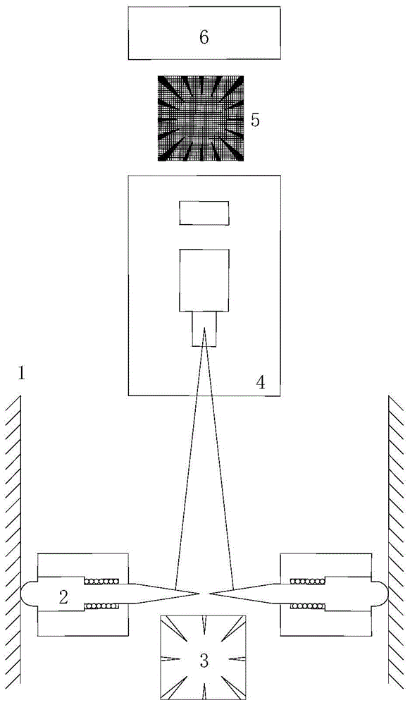
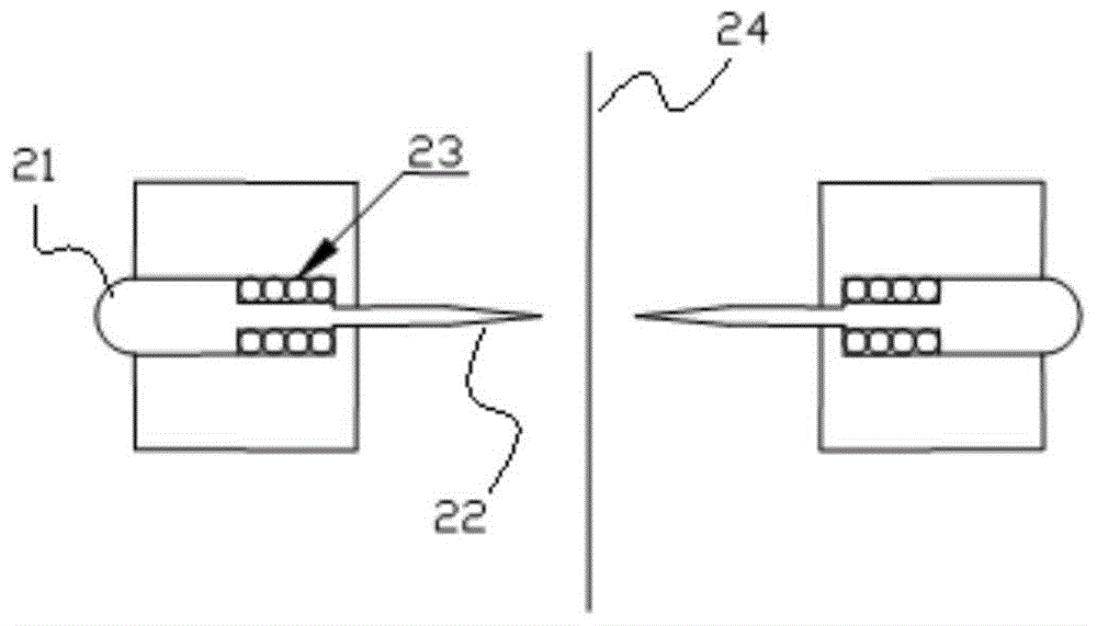
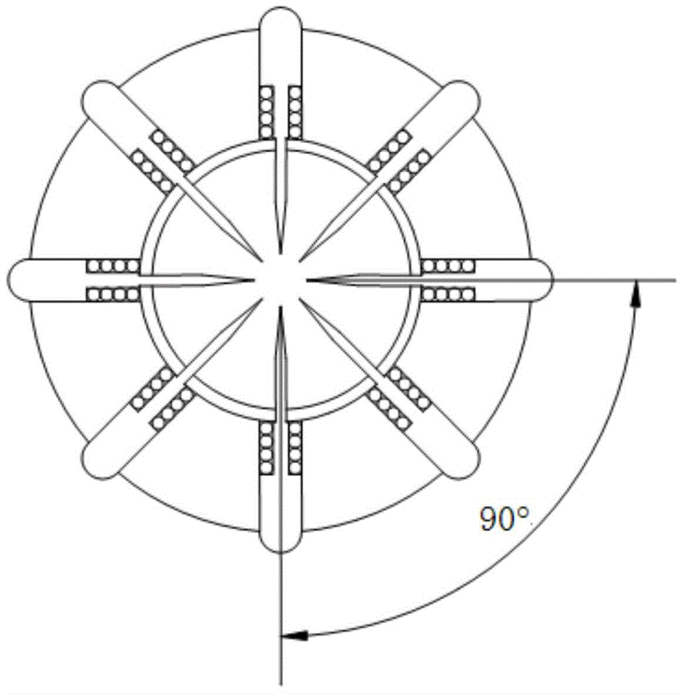
The invention discloses a ground stress test method for aperture distortion optical microscopy measurement. On the basis of ground stress tests of aperture distortion, a design scheme of a multi-contact-probe aperture distortion sensing structure is provided, so that aperture distortion is visual and digital. On the basis of an optical microscopy imaging technology, the technical purposes that micro aperture distortion is visually observed and digitally measured are achieved, and optical microscopy measurement of aperture distortion is achieved. On the basis of theoretical analysis on an aperture distortion principle, a ground stress calculation formula based on aperture distortion optical microscopy measurement is deduced, optimization analysis is carried out on the parameters and the layout of related technologies, and a corresponding software algorithm is built. The ground stress test method for aperture distortion optical microscopy measurement solves main technical problems in ground stress tests of deep holes and ultra-deep holes, the ground stress test technology has ground-breaking substantial progress, and has remarkable scientific significance and economical and practical value.

Description

technical field [0001] The present invention relates to a ground stress test method for optical microscopic measurement of aperture deformation, more specifically to a multi-probe aperture deformation measurement method realized by optical microscopic measurement technology and a ground stress solution method realized by the principle of aperture deformation ;Break through the technical problem that the previous in-situ stress test (mainly based on strain gauges / displacement sensors) cannot be realized in deep and ultra-deep holes, and promote the further development of in-situ stress test technology, which is more suitable for the development and application of shale gas use. Background technique [0002] In-situ stress is the natural stress existing in the rock mass. Its size and distribution are affected by various factors such as the self-weight of the rock mass, geological structure movement, topography and denudation. In-situ stress exists widely, but it is difficult ...

Claims


Application Information

Patent Timeline
Patent Type & Authority Patents(China)
IPC IPC(8): G01B11/16G01L1/24
Inventor 王川婴韩增强胡胜
Owner INST OF ROCK & SOIL MECHANICS CHINESE ACAD OF SCI
Learn More