
Photoetching overlay value calibration method

A calibration method and a technology of overlapping values, which are applied in the photo-engraving process of optics and pattern surface, instruments, etc., can solve the problems of uncontrollable overlapping calibration of the edge of the wafer, and achieve accurate measurement and accurate deposition offset. , the effect of accurate overlapping calibration

Active Publication Date: 2015-01-14
SEMICON MFG INT (SHANGHAI) CORP
View PDF9 Cites 2 Cited by
  • Summary
  • Abstract
  • Description
  • Claims
  • Application Information

AI Technical Summary

Problems solved by technology

[0006] The purpose of the present invention is to solve the problem that the overlay calibration of the existing wafer edge part cannot be controlled

Method used


Image

  • Photoetching overlay value calibration method
  • Photoetching overlay value calibration method
  • Photoetching overlay value calibration method

Examples


Embodiment Construction

[0040] The method for calibrating the iterative value of the lithography of the present invention will be described in more detail below in conjunction with a schematic diagram, wherein a preferred embodiment of the present invention is represented, and it should be understood that those skilled in the art can modify the present invention described herein while still implementing the present invention. Beneficial effects of the invention. Therefore, the following description should be understood as the broad knowledge of those skilled in the art, but not as a limitation of the present invention.

[0041] In the interest of clarity, not all features of an actual implementation are described. In the following description, well-known functions and constructions are not described in detail since they would obscure the invention with unnecessary detail. It should be appreciated that in the development of any actual embodiment, numerous implementation details must be worked out to ...


PUM


Abstract

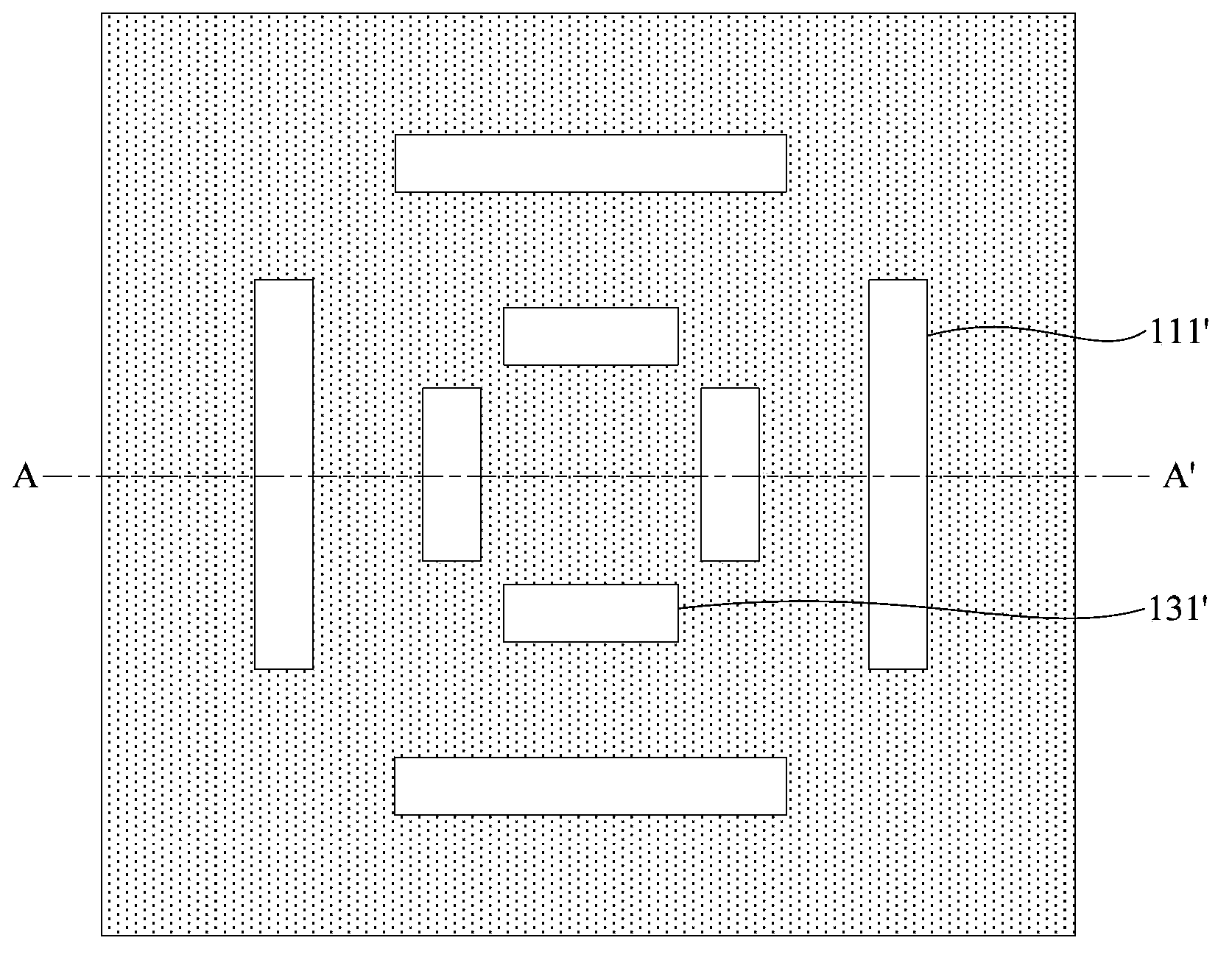
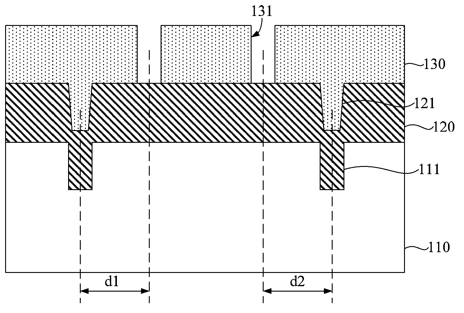
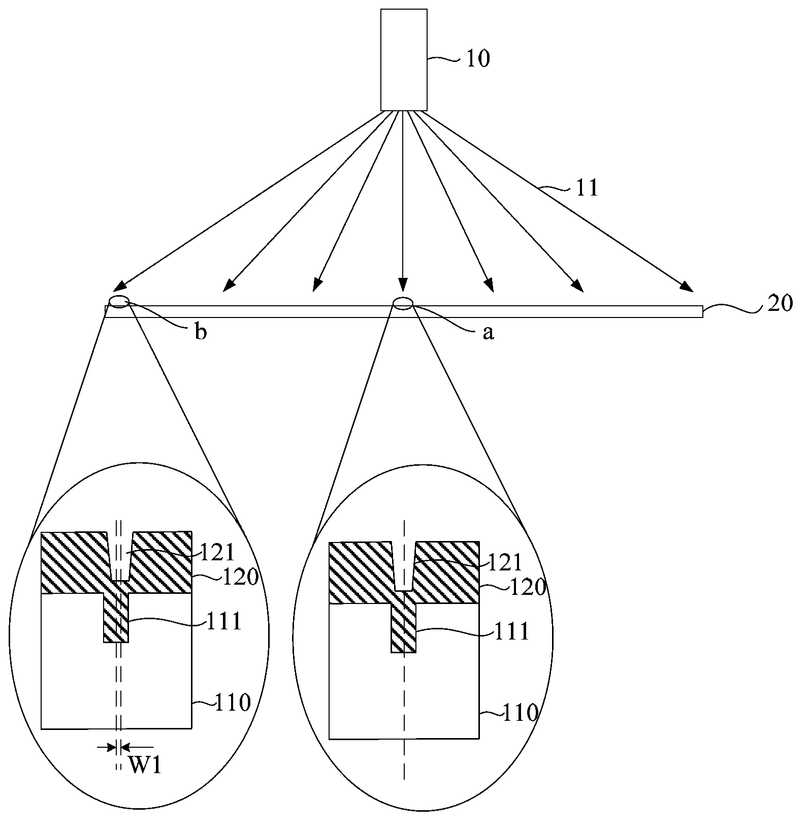
The invention discloses a photoetching overlay value calibration method. The photoetching overlay value calibration method comprises 1, providing a measurement wafer, wherein the measurement wafer comprises a measurement uncompensated overlay zone and at least one measurement compensated overlay zone, the measurement compensated overlay zone is provided with a first groove, an epitaxial layer is deposited in the wafer and the first groove, the epitaxial layer is provided with a second groove corresponding to the first groove and deposition offset is formed between the first groove and the second groove, 2, measuring deposition offset of the at least one measurement compensated overlay zone, 3, providing a wafer to be calibrated, wherein the wafer to be calibrated is provided with an uncompensated overlay zone to be calibrated and at least one compensated overlay zone to be calibrated, and 4, according to the deposition offset, carrying out compensation on the overlay measured data of the corresponding compensated overlay zone to be calibrated so that compensated overlay measured data is obtained. The photoetching overlay value calibration method solves the problem that the prior art cannot control overlay calibration of an edge part of the wafer.

Description

technical field [0001] The invention relates to the field of semiconductor manufacturing, in particular to a photolithography stack value calibration method. Background technique [0002] In the manufacture of a semiconductor device having an overlay structure, an overlay (Overlay) is an index indicating an alignment state of a layer formed in a previous process and a layer formed in a current process. Overlay is very important when developing highly integrated semiconductor devices. In order to detect and calibrate the alignment states of layers formed in a previous process and layers formed in a current process, generally, an overlay between layers is measured by forming an overlay alignment pattern in a scribe line region. The overlay alignment pattern is formed simultaneously with the pattern formed in the device formation region. [0003] Taking the aluminum pad manufacturing process in the semiconductor manufacturing process as an example, the photolithography (photo...

Claims


Application Information

Patent Timeline
IPC IPC(8): G03F9/00
Inventor 刘达
Owner SEMICON MFG INT (SHANGHAI) CORP
Learn More