Photovoltaic module

A photoelectric module and electrical connection technology, applied in the direction of photovoltaic power generation, circuits, electrical components, etc., can solve the problems of increasing module electrical attenuation, adverse effects of module power, etc., and achieve the effect of reducing the risk of electrical attenuation and reducing finger interruption

Active Publication Date: 2015-01-14
MEYER BURGER (GERMANY) GMBH
View PDF3 Cites 7 Cited by
  • Summary
  • Abstract
  • Description
  • Claims
  • Application Information

AI Technical Summary

Problems solved by technology

The occurrence of finger interruptions and battery cracks adversely affects the module power and increases the electrical degradation of the module (Degradation)

Method used


Image

  • Photovoltaic module
  • Photovoltaic module
  • Photovoltaic module

Examples


Embodiment Construction

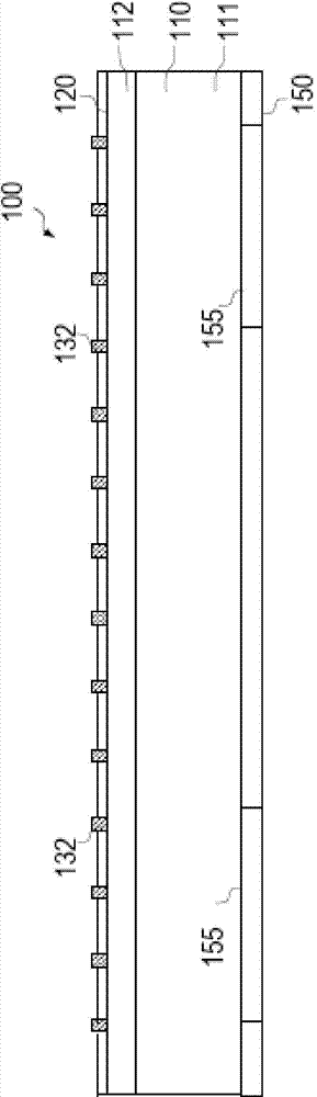
[0023] Solar cells and photovoltaic modules whose improved front-side contact structures are responsible for reducing finger interruptions and cell cracks are described with reference to the accompanying drawings.

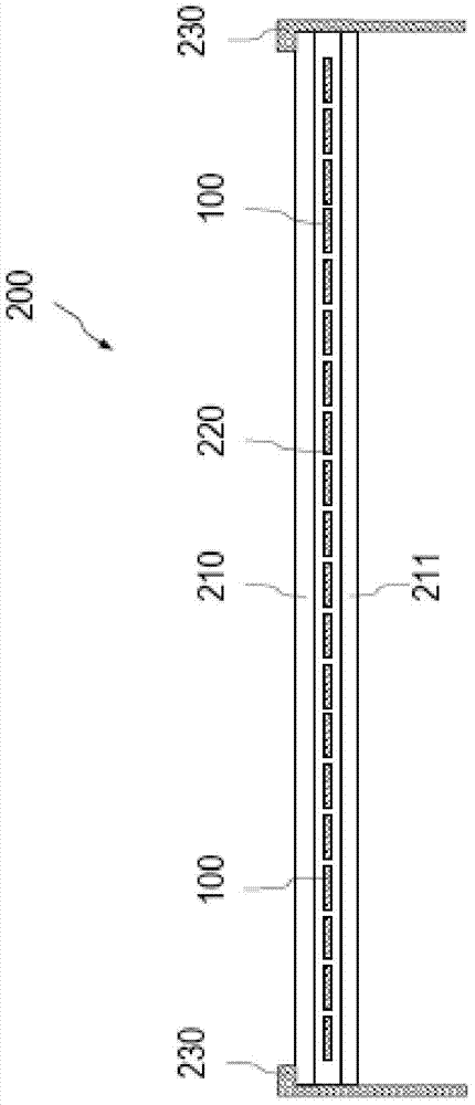
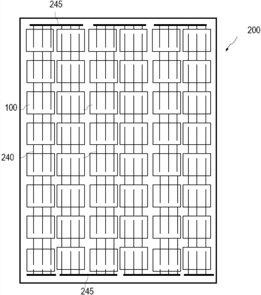
[0024] figure 1 The photovoltaic module 200 is shown in a schematic side view. Figuratively illustrate the attached schematic top view of the front side of the optoelectronic module in figure 2 given in. A photovoltaic module 200 , also referred to below as a solar module, has a number of silicon solar cells 100 that are electrically connected to one another. During operation, the photovoltaic module 200 faces the sun with its front side, a portion of the radiation being absorbed by the solar cells 100 and converted into electrical energy. The solar cell 100 generally has a square structure. However, other shapes can also be realized. The solar cells 100 arranged in a plane in the photovoltaic module 200 are located between the front glass cover 210 and the r...


PUM


Abstract

A photovoltaic module has a number of solar cells, which respectively include a contact structure on a pre-processed silicon wafer, which has a number of linear contact fingers disposed in parallel in a first direction and at least one bus bar disposed perpendicular to the first direction. The bus bar extends over the contact finger in a second direction and has a respective contact surface in the region of the contact finger, which protrudes above the contact finger in the second direction and is electrically connected to the contact fingers. At least one cell connector is provided for connecting the solar cells, which extends over the bus bar of at least one solar cell and is electrically connected to the contact surfaces of the bus bar, wherein the width of the cell connector is smaller than the length of the contact surface in the first direction.

Description

technical field [0001] The invention relates to a photovoltaic module having a plurality of solar cells with a front contact structure comprising a plurality of linear contact fingers arranged in parallel and at least one vertically relative thereto. Distributed busbars. Background technique [0002] Solar cells are used to convert electromagnetic radiation energy, especially sunlight, into electrical energy. The energy conversion is based on the absorption of radiation in the solar cell, whereby positive charge carriers (“electron-hole-pairs”) are generated. The generated free carriers are then separated from each other to be directed to separate contacts. [0003] Solar cells generally have a square silicon substrate in which two regions with different electrical conductivities or dopings are formed. A p-n junction is formed between two regions also called "base" and "emitter". The p-n junction generates an internal electric field that separates the radiation-generated...

Claims


Application Information

Patent Timeline
Patent Type & Authority Applications(China)
IPC IPC(8): H01L31/05
CPCH01L31/0201H01L31/0508H01L31/022433H01L31/0504Y02E10/50
Inventor 赫尔·斯蒂芬·斯特克梅茨赫尔·约尔格·沃尔特马丁·库策亚历山大·菲勒克里斯蒂安·科赫赫尔·弗雷德里克·班贝克
Owner MEYER BURGER (GERMANY) GMBH
Why Eureka
Try Eureka