Lead cast die for molten lead cast

A mold and lead casting technology is applied in the field of non-ferrous metal smelting equipment, which can solve the problems of difficult cleaning of lead slag, pits on the surface of lead ingots, and difficulty in demoulding, and achieves the effect of ensuring the quality of lead ingots, keeping them clean, and being easy to clean.

Inactive Publication Date: 2015-01-21
耒阳市诚松有色金属再生有限公司
View PDF0 Cites 3 Cited by
  • Summary
  • Abstract
  • Description
  • Claims
  • Application Information

AI Technical Summary

Problems solved by technology

However, in actual operation, since the lead liquid will stick to the inner wall of the mold after solidification in the mold, it is difficult to demould. When demoulding with thick iron wire, it will consume the physical strength of the operator; The slag is not easy to clean, which will cause pits on the surface of the lead ingot during the next ingot casting

Method used


Image

  • Lead cast die for molten lead cast
  • Lead cast die for molten lead cast

Examples


Embodiment 1

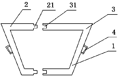
[0018] Such as figure 1 Shown: a cast lead mold for molten lead casting. The mold 1 adopts an inverted trapezoidal structure. The mold 1 is composed of a left mold 2 and a right mold 3. The left mold 2 and the right mold 3 can be symmetrical or asymmetrical The left mold 2 and the right mold 3 are detachable.

[0019] The left mold 2 is provided with two symmetrical protrusions 21 at the connecting end with the right mold 3 , and the right mold 3 is provided with a groove 31 matching the protrusions 21 . The connecting end between the left mold 2 and the right mold 3 can be located at any position of the top and the bottom.

[0020] When in use, insert the two convex strips 21 of the left mold 2 into the two grooves 31 of the right mold 3, and press them tightly. If there is any looseness, you can also chisel a threaded hole at the connecting end of the convex strips 21 and the groove 31. , fixed and pressed with bolts to prevent the left mold 2 from separating from the righ...

Embodiment 2

[0023] The difference from Example 1 is that the left mold 1 is provided with a left bump and a left groove at the connecting end with the right mold 2, and the right mold is provided with a right concave that matches the left bump and the left groove. slot and right tab. When in use, insert the left protrusion into the right groove, and at the same time insert the right protrusion into the left groove and press it tightly.

[0024] Since the structure of this embodiment can be understood by those skilled in the art, it is not shown in the drawings again.

Embodiment 3

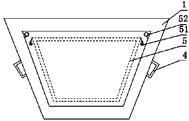
[0026] Such as figure 2 Shown: The difference from Embodiment 1 and Embodiment 2 is that the inner wall of the mold 1 is equipped with a demoulding cylinder 5, and the shape of the demoulding cylinder 5 is the same as that of the mold 1, both of which are inverted trapezoidal structures. Both sides of the demoulding cylinder 5 are provided with hooks 51 , and the mold 1 is provided with suspension rings 52 at positions corresponding to the hooks 51 , so that the demoulding cylinder 5 is detachably fixed on the inside of the mold 1 . The demoulding cylinder 5 is a smooth ceramic material, and the mold 1 is a stainless steel material.

[0027] The method of use in this embodiment is as follows: the demoulding cylinder 5 is fixed on the inner wall of the mold 1, the mold 1 is fixed on the trolley, and transported to the outlet of the chute, the lead liquid flows into the demoulding cylinder 5 through the chute, and then passes through the After air cooling and cooling water spr...


PUM


Abstract

A lead cast die for molten liquid cast is characterized in that the die is of an inverted trapezoid structure, the die is composed of a left die body and a right die body in symmetry, and the left die body and the right die body are detachable. According to the lead cast die, on one hand, an operator can smoothly release the die, and time and labor are saved; on the other hand, lead ingot quality and cleanness of the inner wall of the die are guaranteed.

Description

technical field [0001] The invention relates to the field of nonferrous metal smelting equipment, in particular to a cast lead mold for casting lead liquid. Background technique [0002] The lead casting mold is fixed on the trolley to mold the lead liquid into an ingot. The lead liquid flows into the lead casting mold through the chute, and after being cooled by air and sprayed with cooling water, it solidifies to form lead blocks. When the lead liquid is about to solidify, a thick iron wire is usually placed in the center of the mold and inserted into the lead liquid. After the lead block is made, the lead block is picked up by the thick iron wire and pulled out from the mold to obtain a lead ingot with the same shape as the mold. However, in actual operation, since the lead liquid will stick to the inner wall of the mold after solidification in the mold, it is difficult to demould. When demoulding with thick iron wire, it will consume the physical strength of the operato...

Claims


Application Information

Patent Timeline
Patent Type & Authority Applications(China)
IPC IPC(8): B22D7/08
CPCB22D7/08
Inventor 陈松陈凯
Owner 耒阳市诚松有色金属再生有限公司
Why Eureka
Try Eureka