Longitudinal gravity compensation device with micro-gravity simulation implementation systems and six degrees of freedom for spatial mechanisms
A microgravity simulation and realization system technology, which is applied to the simulation device of space navigation conditions, transportation and packaging, space navigation equipment, etc., can solve the problems such as difficult to realize longitudinal gravity compensation, achieve the elimination of mechanical friction interference force and high compensation accuracy , Compensate for the effect of large gravity
- Summary
- Abstract
- Description
- Claims
- Application Information
AI Technical Summary
Problems solved by technology
Method used
Image
Examples
specific Embodiment approach 1
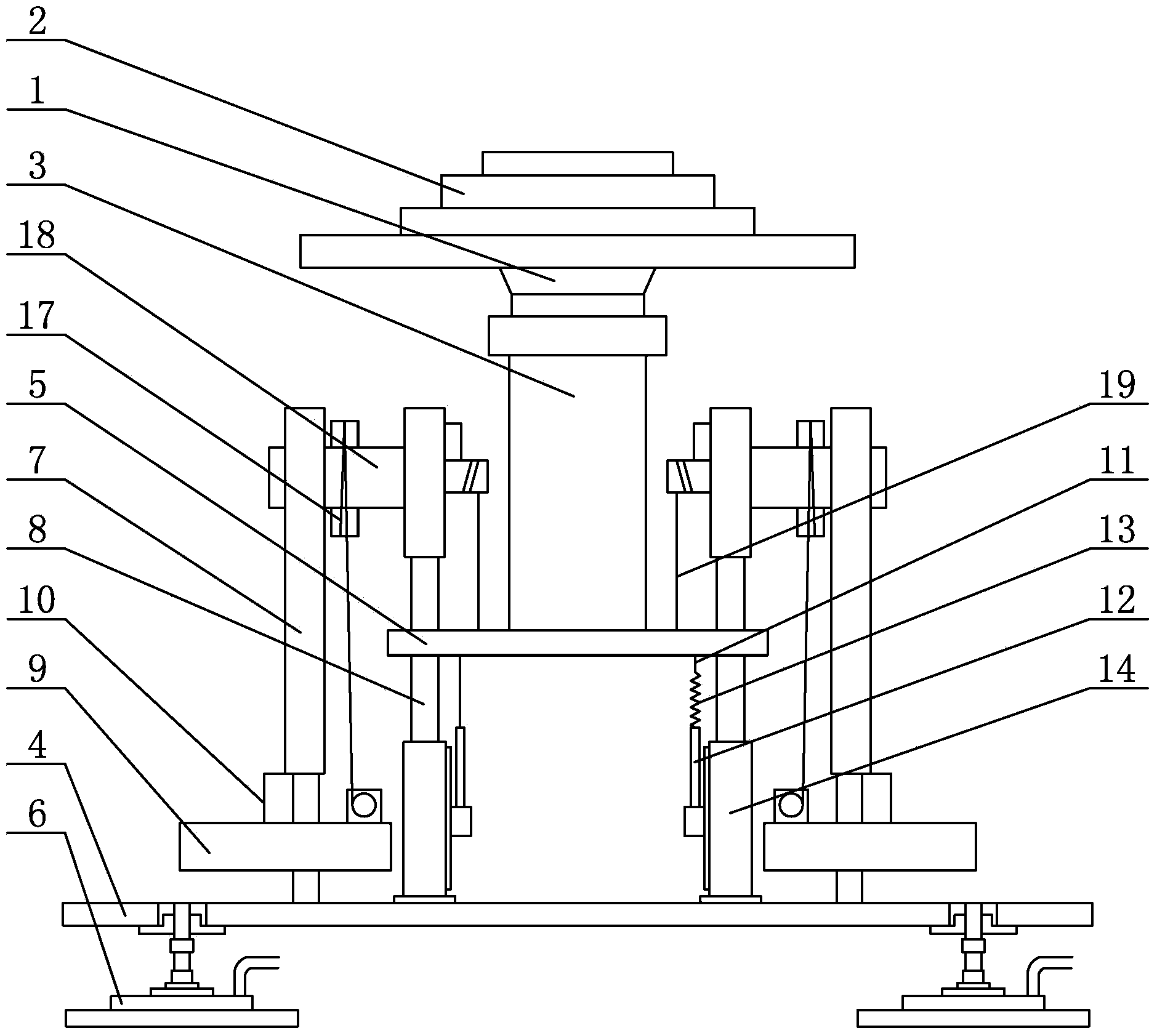
[0008] Specific implementation mode one: combine figure 1 To illustrate this embodiment, the longitudinal gravity compensation device of the six-degree-of-freedom microgravity simulation realization system of the space mechanism in this embodiment includes a ball bearing 1, an upper platform 2, a central column 3, a lower platform 4, an intermediate platform 5, and four air feet 6 and four compensation systems, the upper platform 2, the middle platform 5, and the lower platform 4 are arranged sequentially from top to bottom, the central column 3 is vertically arranged between the lower surface of the upper platform 2 and the upper surface of the middle platform 5, and the central column 3 The upper end of the upper platform is connected with the lower surface of the upper platform 2 through the ball bearing 1, the lower end of the central column 3 is connected with the upper surface of the middle platform 5, and the four compensation systems are arranged in a square on the uppe...
specific Embodiment approach 2
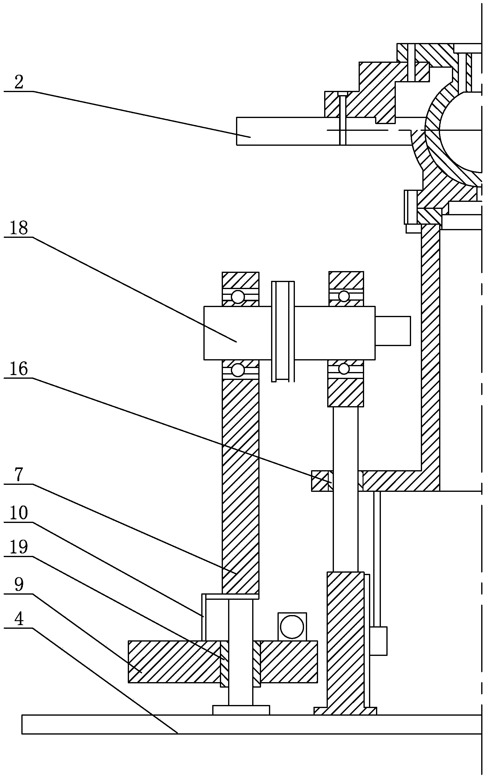
[0009] Specific implementation mode two: combination figure 1 and figure 2 Describe this embodiment, each of the compensation systems in the longitudinal gravity compensation device of the space mechanism six-degree-of-freedom microgravity simulation realization system in this embodiment includes a cable receiving mechanism, an outer support column 7, an inner support column 8, and a counterweight 9 , Hall displacement sensor 10, pressure sensor 11, connecting rod 12, spring 13, linear motor 14, outer column radial bearing 15, inner column radial bearing 16, stepped shaft 18 and second steel wire rope 19, counterweight 9 passes The radial bearing 15 of the outer column is set on the lower part of the outer support column 7, the upper surface of the counterweight 9 is connected with the outer wall of the outer support column 7 through the Hall displacement sensor 10, and the linear motor 14 is installed on the upper surface of the lower platform 4 , the lower end of the inner...
specific Embodiment approach 3
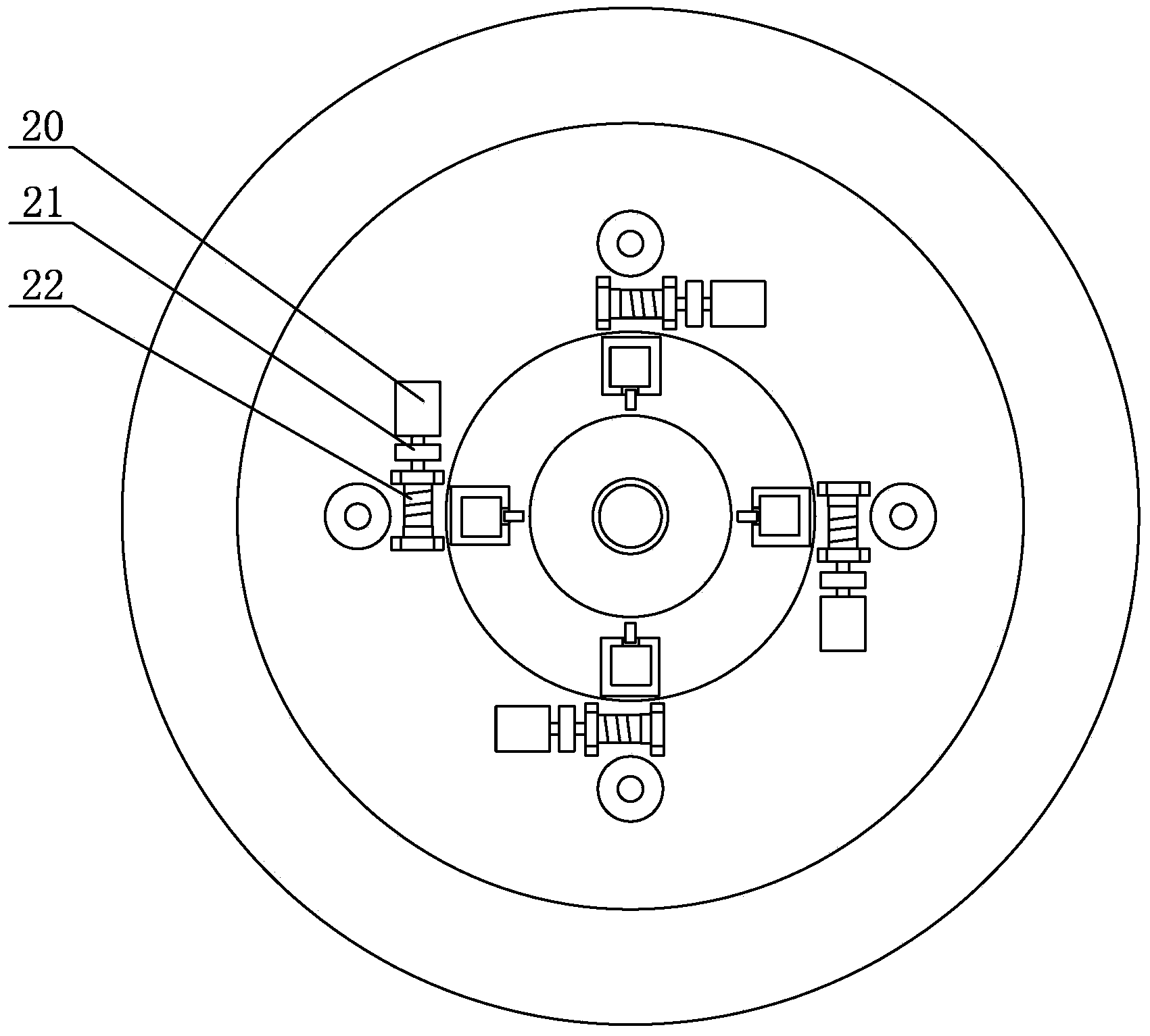
[0011] Specific implementation mode three: combination Figure 1 to Figure 3 To illustrate this embodiment, each of the cable-receiving mechanisms of the six-degree-of-freedom microgravity simulation realization system of the spatial mechanism in this embodiment includes a first steel wire rope 17, a servo motor 20, a reducer 21, and a cable-receiving reel. 22. The rotating shaft of the servo motor 20 is connected to the cable reel 22 through the reducer 21, one end of the first steel wire rope 17 is connected to the cable reel 22, and the other end of the first steel cable 17 is connected to the stepped shaft 18. Other components and connections are the same as those in the second embodiment.
[0012] working principle
[0013] The passive proportional counterweight mechanism is mainly composed of counterweight, stepped shaft, supporting column, cable receiving servo mechanism and several bearings. The stepped shaft has four steps, of which two shafts are rotary bearings, an...
PUM
 Abstract
Description
Claims
Application Information
 - R&D
- Intellectual Property
- Life Sciences
- Materials
- Tech Scout
- Unparalleled Data Quality
- Higher Quality Content
- 60% Fewer Hallucinations
Browse by: Latest US Patents, China's latest patents, Technical Efficacy Thesaurus, Application Domain, Technology Topic, Popular Technical Reports.
© 2025 PatSnap. All rights reserved.Legal|Privacy policy|Modern Slavery Act Transparency Statement|Sitemap|About US| Contact US: help@patsnap.com


