Hydraulic self-ploughing type sludge suction head

A mud suction head and self-cultivation technology, which is applied in the direction of mechanically driven excavators/dredgers, etc., to achieve the effects of reduced operating costs, high working efficiency, and increased torque

Inactive Publication Date: 2015-01-21
HOHAI UNIV
View PDF8 Cites 1 Cited by
  • Summary
  • Abstract
  • Description
  • Claims
  • Application Information

AI Technical Summary

Problems solved by technology

The disadvantage of this device is that it needs to provide a lot of power energy to vibrate the silt, and use the suction pump to discharge the silt

Method used


Image

  • Hydraulic self-ploughing type sludge suction head

Examples


Embodiment Construction

[0016] The specific implementation manners of the present invention will be further described in detail below in conjunction with the drawings and examples.

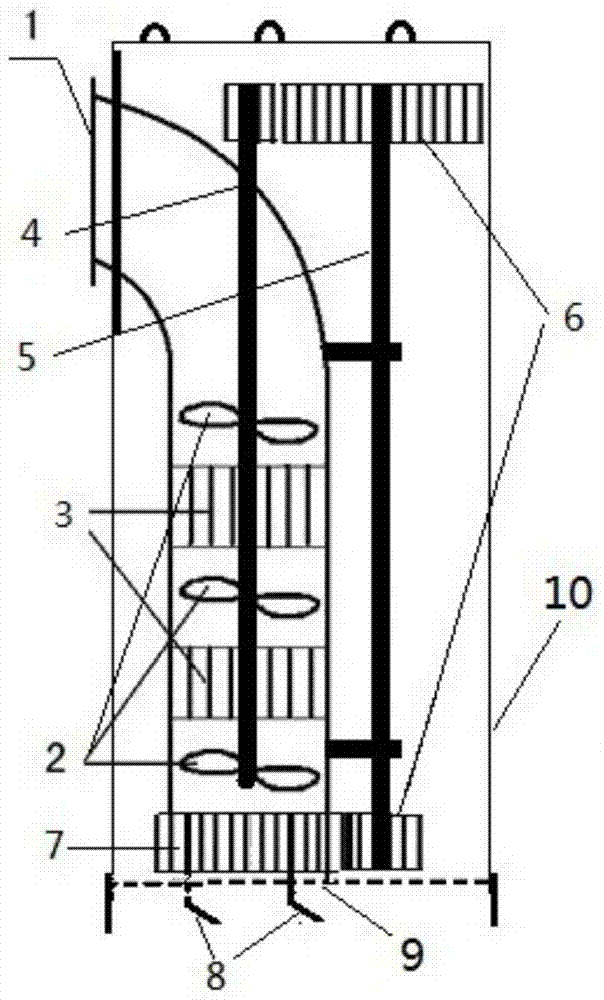
[0017] combine figure 1 , a hydraulic self-cultivation mud suction head proposed by the present invention, which includes a steel pipe (1), an impeller group (2), a rectifier (3), a driving shaft (4), a driven shaft (5), a gear set ( 6), bearing (7), plow (8), filter screen (9) and protective cover (10), wherein: the impeller group (2) and rectifier (3) are arranged in the steel pipe (1), and the rectifier (3) Fixed on the inner wall of the steel pipe (1), the drive shaft (4) passes through the bearing in the center of the rectifier (3), the gear set (6) is fixed on the drive shaft (4) and the driven shaft (5), The bearing (7) is embedded in the gear, the plow (8) is welded on the gear set (6), the filter screen (9) is set on the water inlet of the steel pipe (1), and the protective cover (10) encapsulates the abov...


PUM


Abstract

The invention relates to a hydraulic self-ploughing type sludge suction head. The hydraulic self-ploughing type sludge suction head is characterized in that a steel pipe, impeller sets, rectification sheets, a driving shaft, a driven shaft, gear sets, bearings, plows, a filter screen and a protection cover are included. The impeller sets and the rectification sheets are arranged in the steel pipe, the rectification sheets are fixed to the inner wall of the steel pipe, the driving shaft penetrates through the bearings in the centers of the rectification sheets, the gear sets are fixed to the driving shaft and the driven shaft, the bearings are embedded in gears, the plows are welded to the gear sets, a water inlet of the steel pipe is sleeved with the filter screen, and all the components are sealed in the protection cover. Impellers in the steel pipe can be driven by the energy of high-speed water flow in an outer sand conveying pipeline to rotate at high speed, sludge settled at the bottom of a reservoir can be easily stirred by force finally acting on the plows, and the effect of integrally reservoir underwater dredging and sand discharging can be achieved without other power source devices.

Description

technical field [0001] The invention belongs to the technical field of water conservancy engineering, and in particular relates to a hydraulic self-cultivation dredging head for removing silt deposited in a reservoir. [0002] Background technique [0003] There are 86,000 reservoirs in my country, most of which were built in the 1950s and 1960s. They lack effective sediment discharge design. After many years of operation, sedimentation has generally occurred, which has seriously reduced the capacity of the reservoir. The silt deposition in the reservoir reduces the storage capacity of the reservoir and reduces the water storage capacity, especially in the northwest region, where the rivers have a large amount of sediment, and the reservoirs silted up by the silt even completely lose their reservoir functions. Some reservoirs are designed with sand discharge bottom holes, but they can only discharge the sediment near the bottom hole door, and the large flow of sand discha...

Claims


Application Information

Patent Timeline
Patent Type & Authority Applications(China)
IPC IPC(8): E02F3/92
Inventor 舒大兴
Owner HOHAI UNIV
Why Eureka
Try Eureka