Double-ball connecting rod connection device used for vehicle lamp adjustable support connection

A ball-end connecting rod and connecting device technology, which is applied in the direction of headlights, signal devices, lighting devices, etc., can solve the problems such as the large volume of the connecting rod 5', the reduction of motor life, the increase of the overall volume of the far and near beam units, etc. The effect of compactness, improved motor life, and simple structure

Active Publication Date: 2015-01-21
HASCO VISION TECHNOLOGY CO LTD
View PDF6 Cites 16 Cited by
  • Summary
  • Abstract
  • Description
  • Claims
  • Application Information

AI Technical Summary

Problems solved by technology

[0004] However, the disadvantages of the above-mentioned single-link connection method are:
[0005] Since the ball socket 5'b and the ball head 5'c of the connecting rod 5' cannot be arranged in a straight line, the volume of the connecting rod 5' is relatively large, and the two adjustable brackets 3' and 4' need to be adjusted according to the connecting rod 5'. The positions of the ball socket 5'b and the ball head 5'c are staggered horizontally, resulting in an increase in the overall volume of the far and near light unit
[0006] In addition, since the ball socket 5'b and the ball head 5'c of the connecting rod 5' cannot be arranged in a straight line, the force direction of the ball socket 5'b and the ball head 5'c of the connecting rod 5' is the same as that of the motor ball head. There is a certain distance in the direction of motion of 1'a, which generates torque and causes lateral force on the motor ball head 1'a, reducing the life of the motor

Method used


Image

  • Double-ball connecting rod connection device used for vehicle lamp adjustable support connection
  • Double-ball connecting rod connection device used for vehicle lamp adjustable support connection
  • Double-ball connecting rod connection device used for vehicle lamp adjustable support connection

Examples


Embodiment 1

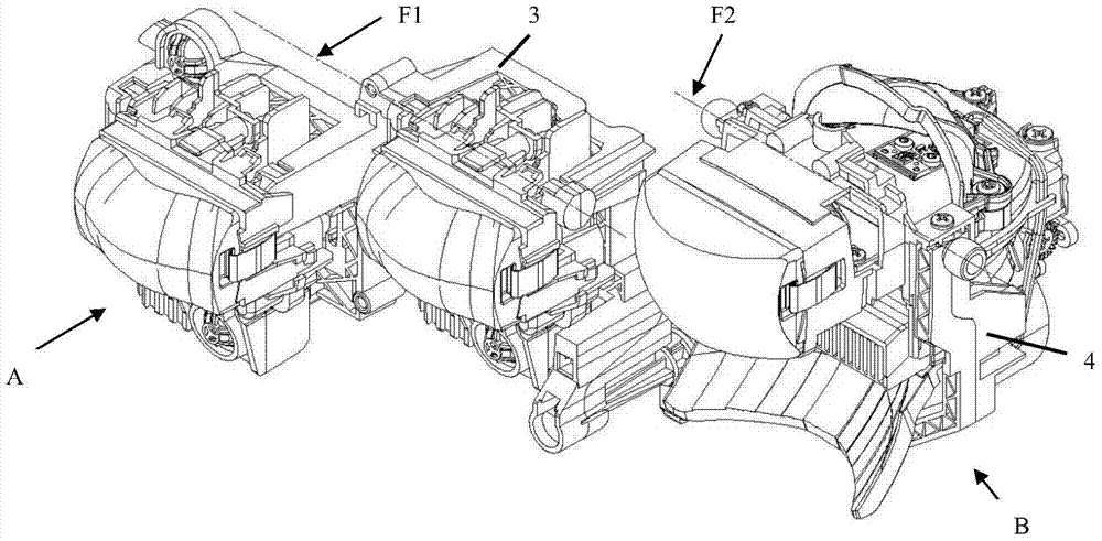
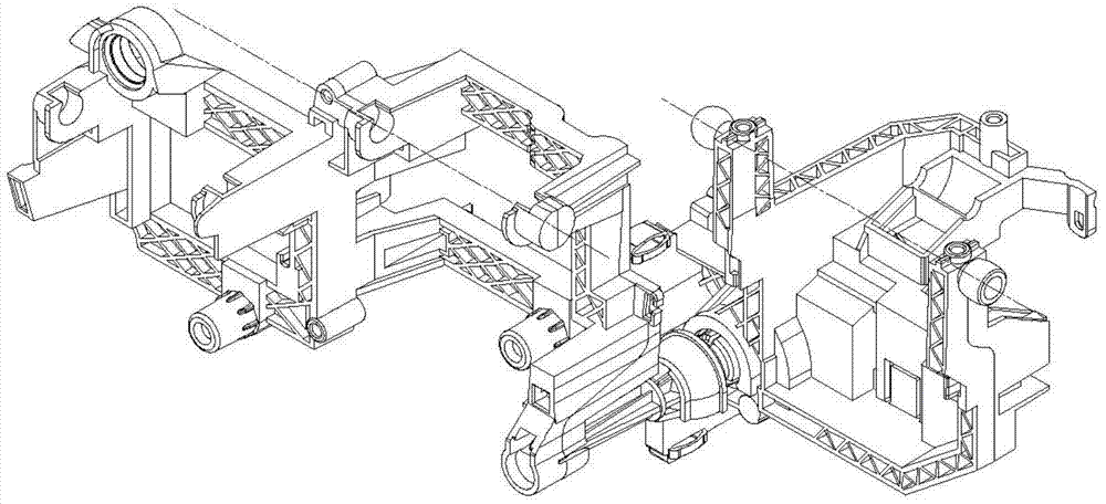
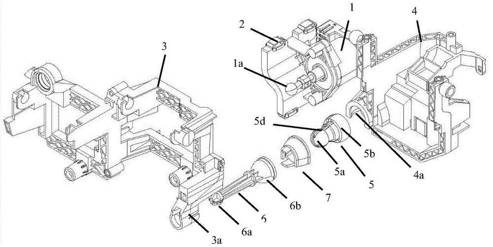
[0054] like Figure 1-9 As shown, a double-ball-joint link connecting device used for connecting the adjustable bracket of the vehicle lamp, the double-ball-joint link connecting device is arranged at the lower corner of the first adjustable bracket 3 of the first light-emitting unit B. It is used for the connection and synchronous adjustment of tilting up and down of the adjustable bracket of multiple light-emitting units of the car lamp, including: the first adjustable bracket 3 for connecting and synchronously adjusting the first light-emitting unit B and the second of the second light-emitting unit C The double ball-joint connecting rod 5 that the adjustable support 4 tilts up and down.

[0055] The second adjustable bracket 4 of the second lighting unit B is placed behind the first adjustable bracket 3 of the first lighting unit A. The first light-emitting unit A is connected to another light-emitting unit B that is dislocated integrally with it, and the first adjustable...


PUM


Abstract

A double-ball connecting rod connection device used for vehicle lamp adjustable support connection comprises a double-ball connecting rod (5) used for connecting and synchronously adjusting a plurality of light-emitting units (A). A cavity type first ball (5a) and a cavity type second ball (5b) are arranged at the two ends of the double-ball connecting rod (5) respectively. A ball socket (5c) is arranged inside the cavity type first ball (5a). The two ends of the double-ball connecting rod (5) are connected with second adjustable supports of different light-emitting units respectively. A motor ball (1a) of a motor (1) penetrates through the cavity type second ball (5b) and is matched with the ball socket (5c) in the first ball (5a) to form a rotating pair. According to the double-ball connecting rod connection device, the adjustable supports of two or more light-emitting units can be synchronously and vertically adjusted in a tilting mode, and therefore the aim of synchronously adjusting different light-emitting units in a vehicle lamp is achieved. In addition, compared with the prior art, the overall size of a high-beam unit and the overall size of a low-beam unit of the double-ball connecting rod connection device are reduced, the transverse stress of the motor ball is reduced, and the service life of the motor is prolonged.

Description

technical field [0001] The present invention relates to a car lamp connection structure, in particular, the present invention relates to a double-ball-joint connecting-rod connecting device used for adjustment between adjustable brackets in a car lamp, and the double-ball-joint connecting-rod connecting device is used in a car The light-emitting unit of the lamp is adjusted by tilting up and down, so that the adjustable supports of two or more light-emitting units can be adjusted by tilting up and down synchronously. Background technique [0002] Because the far and near beam lighting functions in the car lights are usually composed of different lighting units, and are respectively fixed on different adjustable brackets. At the same time, due to the angle deviation between the vehicle and the road surface caused by the vehicle under different loads and different road surface conditions, it is necessary to dynamically adjust the illumination of the far and near beams accordin...

Claims


Application Information

Patent Timeline
Patent Type & Authority Applications(China)
IPC IPC(8): F21V21/14F21W101/02F21W107/10
CPCF21S41/00F21V21/29B60Q1/076B60Q2200/36
Inventor 张洁罗思蓉
Owner HASCO VISION TECHNOLOGY CO LTD
Why Eureka
Try Eureka