Fiber Bragg Grating Vibration Sensor for Sensitization Platform
A technology of vibration sensor and optical fiber grating, which is applied to instruments, measuring devices, and measuring ultrasonic/sonic/infrasonic waves, etc. It can solve the problems of sensor head processing, installation difficulties, and low sensor sensitivity, so as to improve sensitivity and shorten the force range. Effect
- Summary
- Abstract
- Description
- Claims
- Application Information
AI Technical Summary
Problems solved by technology
Method used
Image
Examples
Embodiment 1
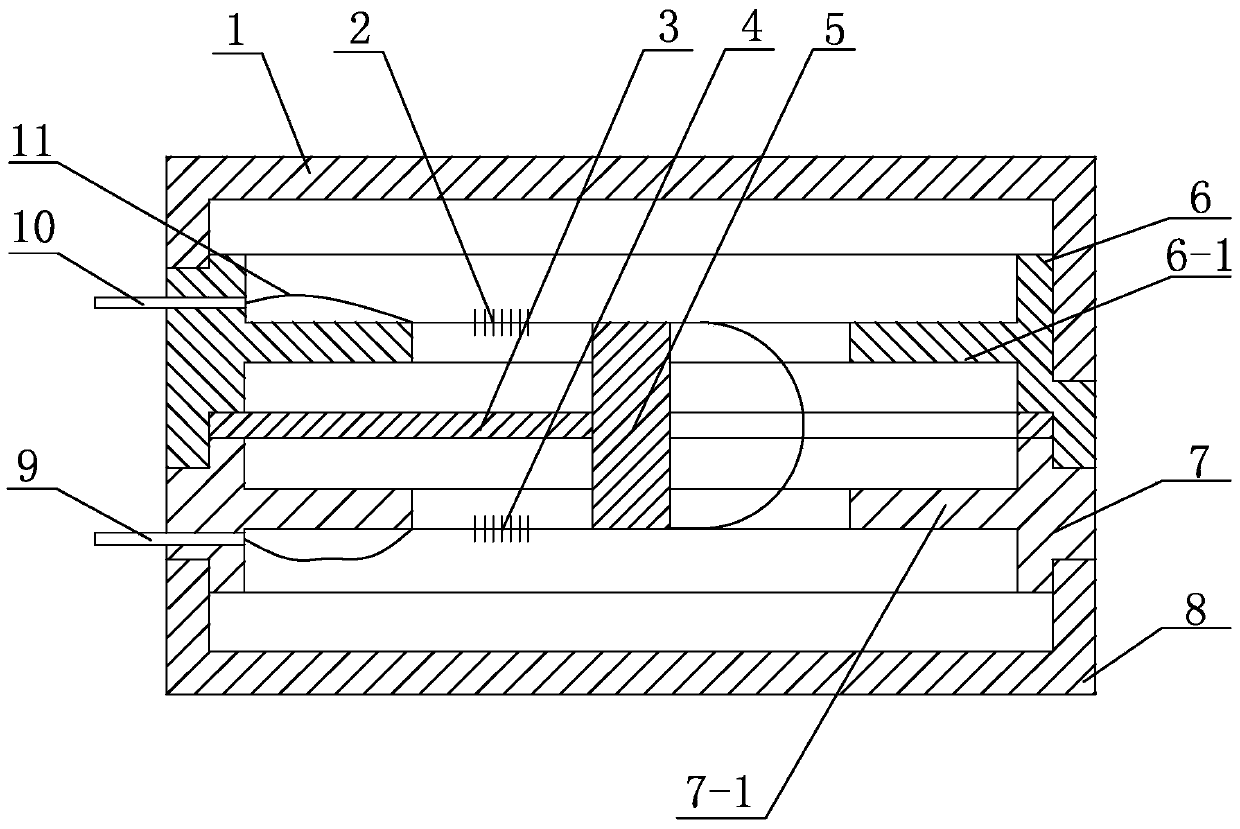
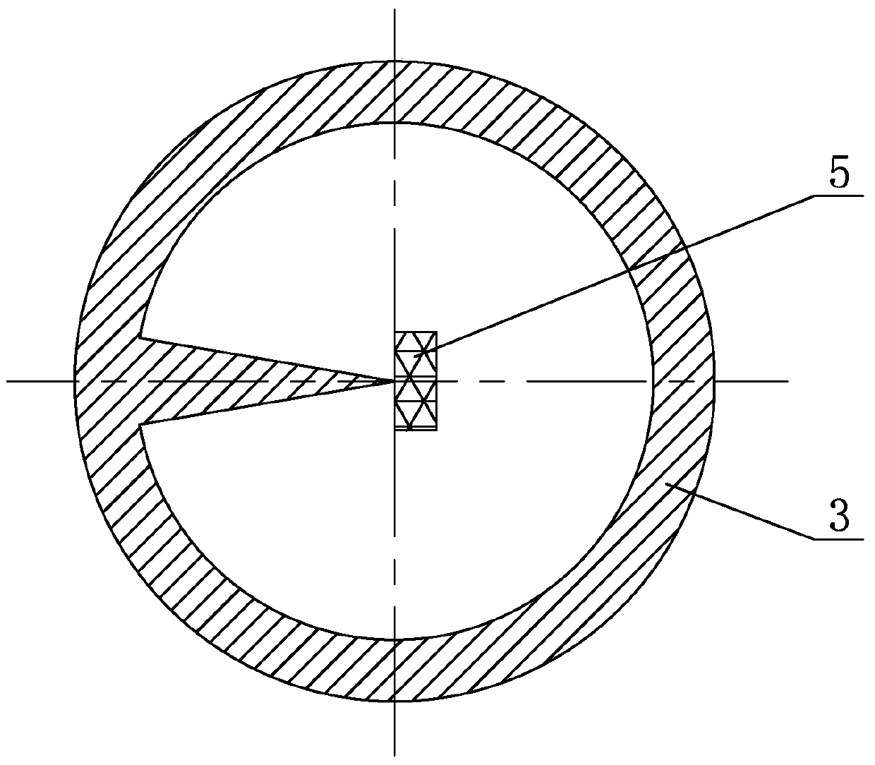
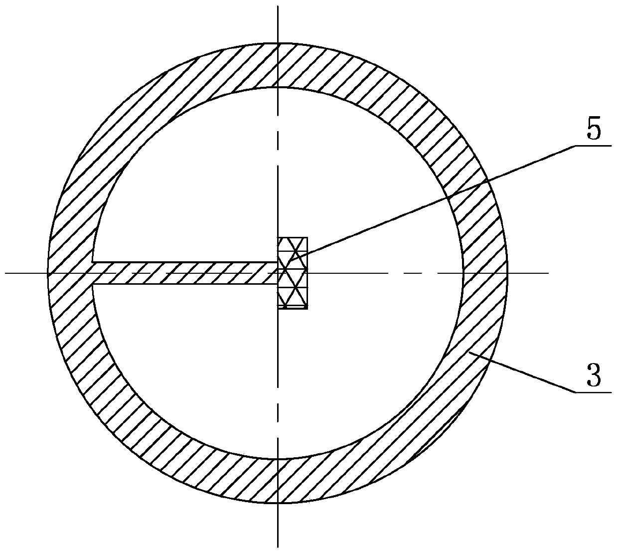
[0017] exist Figure 1 ~ Figure 2 Among them, the fiber grating vibration sensor of the sensitization platform of this embodiment consists of an upper cover 1, an upper sensing grating 2, a cantilever beam 3, a lower sensing grating 4, a mass 5, an upper sensitization platform 6, a lower sensitization platform 7, a lower The cover 8, the lower optical fiber tube 9, the upper optical fiber tube 10, and the optical fiber 11 are connected to form.
[0018] The geometric shape of the upper sensitization platform 6 in this embodiment is a ring structure, and the upper sensitization platform 6 is connected as a whole with an upper sensing grating fixing ring 6-1, and the upper sensing grating fixing ring 6-1 is a ring structure. The upper left side of the upper sensitivity enhancement platform 6 above the upper sensing grating fixing ring 6-1 is provided with an upper optical fiber tube 10 through threaded connection, and the lower end of the upper sensitivity enhancement platform 6...
Embodiment 2
[0024] In this embodiment, the distance between the left end of the proof mass 5 and the inner edge of the upper sensing grating fixing ring 6-1 is 5mm. The upper part of an optical fiber 11 is pasted on the upper surface of the upper sensing grating fixing ring 6-1 and the upper surface of the quality block 5 with a model 353 epoxy glue, and the lower part is pasted on the lower part with a model 353 epoxy glue. The lower surface of the grating fixing ring 7-1 and the lower surface of the quality block 5, the upper part of the optical fiber 11 is written with the upper sensing grating 2, and the lower part is written with the lower sensing grating 4, the wavelength of the upper sensing grating 2 is 1500nm, the upper grating The area length is 2mm, the wavelength of the lower sensing grating 4 is 1500nm, and the length of the lower grid area is 2mm. 3 times the distance between the surface and the lower surface of the lower sensing grating fixing ring 7-1. Other components an...
Embodiment 3
[0026] In this embodiment, the distance between the left end of the proof mass 5 and the inner edge of the upper sensing grating fixing ring 6-1 is 10 mm. The upper part of an optical fiber 11 is pasted on the upper surface of the upper sensing grating fixing ring 6-1 and the upper surface of the quality block 5 with a model 353 epoxy glue, and the lower part is pasted on the lower part with a model 353 epoxy glue. The lower surface of the grating fixing ring 7-1 and the lower surface of the quality block 5, the upper part of the optical fiber 11 is written with the upper sensing grating 2, and the lower part is written with the lower sensing grating 4, the wavelength of the upper sensing grating 2 is 1600nm, and the upper grating The area length is 4mm, the wavelength of the lower sensing grating 4 is 1600nm, the length of the lower grid area is 4mm, and the length of the optical fiber 11 between the upper sensing grating 2 and the lower sensing grating 4 is the upper sensing ...
PUM
 Abstract
Description
Claims
Application Information
 - R&D Engineer
- R&D Manager
- IP Professional
- Industry Leading Data Capabilities
- Powerful AI technology
- Patent DNA Extraction
Browse by: Latest US Patents, China's latest patents, Technical Efficacy Thesaurus, Application Domain, Technology Topic, Popular Technical Reports.
© 2024 PatSnap. All rights reserved.Legal|Privacy policy|Modern Slavery Act Transparency Statement|Sitemap|About US| Contact US: help@patsnap.com


