Reactor core iterative design system based on Monte Carlo calculation

An iterative design and reactor technology, applied in the field of reactor core iterative design system, can solve problems such as the inability to analyze the hierarchical structure of the Monte Carlo calculation model, the inability to complete the iterative modification of the core geometry, and the failure to prove the repeated iterative design of the core, etc., to achieve Improve modeling efficiency, avoid low visualization efficiency, and make the design process clear and clear

Active Publication Date: 2015-01-21
HEFEI INSTITUTES OF PHYSICAL SCIENCE - CHINESE ACAD OF SCI
View PDF2 Cites 23 Cited by
  • Summary
  • Abstract
  • Description
  • Claims
  • Application Information

AI Technical Summary

Problems solved by technology

The fission core rapid modeling module developed in MCAM earlier cannot analyze the hierarchical structure in the Monte Carlo calculation model, nor can it complete the iterative modification of the core geometry, and cannot be applied in the design of the actual core
Subsequently, the Beijing Institute of Applied Physics and Computational Mathematics and the Argonne National Laboratory in the U

Method used


Image

  • Reactor core iterative design system based on Monte Carlo calculation
  • Reactor core iterative design system based on Monte Carlo calculation
  • Reactor core iterative design system based on Monte Carlo calculation

Examples


Embodiment 1

[0078] The goal is to use the present invention to complete the construction of a fast neutron reactor core. The upper and lower grid parameters are shown in Table 1, the fuel rod parameters are shown in Table 2, and other parameters are shown in Table 3. After the modeling is completed, part of the design optimization is carried out.

[0079] Table 1: Upper and lower grid parameters

[0080] Material

S32168

diameter

798mm

thickness

5mm

hole diameter

7.9mm

Distance between upper and lower grid plates

400mm

Support hole diameter

41mm

Support hole height

400mm

Support column material

S32168

Distance from support hole to center

325mm

[0081] Table 2: Fuel Rod Parameters

[0082]

[0083] Table 3: Other parameters

[0084]

[0085] The first step is to input the modeling parameters through the interface provided by the system;

[0086] In the second step, click t...

Embodiment 2

[0090] The goal is to parse the original Monte Carlo calculation model file and perform iterative design;

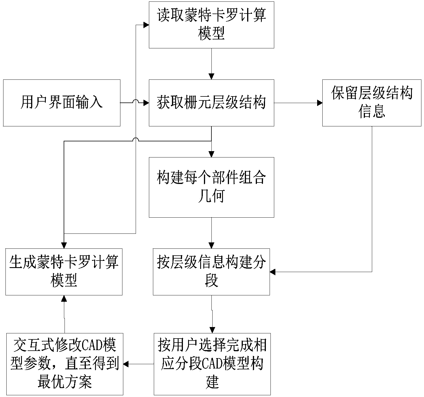
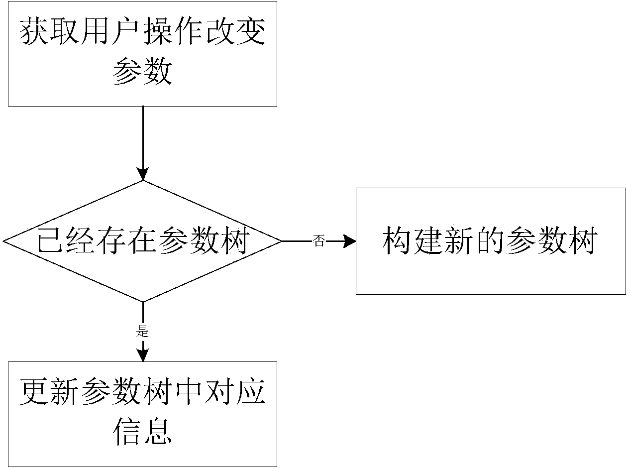
[0091] The first step is to import the MCNP program calculation model file. Figure 12 As shown, it is an existing Monte Carlo calculation model, which can be imported into the calculation model analysis module to complete the construction of the parameter tree.

[0092] The second step is to obtain the CAD engineering model. Such as Figure 13 As shown, it is the core CAD engineering model generated in this embodiment, imported Figure 12 After the Monte Carlo calculation model is shown and the parameter tree is built inside the system, this CAD engineering model is generated;

[0093] The third step is to visually render the CAD engineering model;

[0094] The fourth step is to modify the rendered 3D model through the interface modification function;

[0095] The fifth step is to output the new MCNP program calculation model file.


PUM


Abstract

The invention discloses a modeling system which is used in reactor design and used for reactor core component design. According to the modeling system, the geometric specificity of a fission reactor core is analyzed, a great amount of repeatedly constructed geometries are adopted, a CAD engineering model and a Monte Carlo calculation model of the fission reactor core are automatically established by establishing parameters, the Monte Carlo calculation model is used for radiating and transporting input of a Monte Carlo calculation program, and the significant physical quantity of the reactor core can be calculated after the Monte Carlo calculation model is obtained. By constantly evaluating the physical parameters of the calculation result, the modeling system can be used for performing repeated iteration correction on a design scheme of the fission reactor core till a reactor core scheme which makes a user satisfactory is made. The modeling system has the benefits that the tediousness that Monte Carlo calculation programs are written and files are input manually is avoided, the whole modeling process is very visible, the probability of mistakes is greatly reduced, and the design time of the reactor core is shortened.

Description

technical field [0001] The invention relates to a reactor core iterative design system based on Monte Carlo calculation, which is applied in the fission reactor core design based on Monte Carlo calculation, and the goal is to quickly and automatically build a fission reactor core CAD engineering model and Monte Carlo calculation Model. Background technique [0002] With the advancement of reactor design and construction technology, various new reactor designs have come out frequently. The Monte Carlo calculation program has been widely used in the conceptual design and engineering design of the core due to its ability to adapt to any complex geometry and accurate calculation results. , and completing the modeling of complex geometry is the core part of writing the input file of the calculation program. At present, the following methods are mainly used: first, manual modeling is time-consuming and labor-intensive, and is prone to errors; second, automatic modeling by script ...

Claims


Application Information

Patent Timeline
IPC IPC(8): G06F17/50G06T17/00G06T15/00
Inventor 甘佺俞盛朋程梦云汪冬吴宜灿
Owner HEFEI INSTITUTES OF PHYSICAL SCIENCE - CHINESE ACAD OF SCI
Why Eureka
Try Eureka