Method for improving color errors, color error adjustment structure and display device

A technology for improving color shift and color coordinates, applied in static indicators, instruments, etc., can solve problems such as affecting the image quality of LCD modules, poor uniformity of color coordinates of white mixed light, etc., and achieve the effect of improving color shift and improving uniformity.

Active Publication Date: 2015-01-21
BOE TECH GRP CO LTD +1
View PDF4 Cites 26 Cited by
  • Summary
  • Abstract
  • Description
  • Claims
  • Application Information

AI Technical Summary

Problems solved by technology

In this structure, due to the different absorption and dispersion capabilities of the light guide plate for visible light of different wavelengths, the uniformity of visible light of different wavelengths on the light guide plate is different, so the color coordinate uniformity of the white mixed light emitted by the light guide plate is poor.
In addition, due to equipment and process fluctuations in the LCD panel manufacturing process, differences in chromaticity on the LCD panel can be avoided.
Chromaticity uniformity caused by BLU (backlight unit) and panel affects the picture quality of LCD module

Method used


Image

  • Method for improving color errors, color error adjustment structure and display device
  • Method for improving color errors, color error adjustment structure and display device
  • Method for improving color errors, color error adjustment structure and display device

Examples


Embodiment Construction

[0039] The structure and principle of the present invention will be described in detail below in conjunction with the accompanying drawings, and the examples given are only used to explain the present invention, not to limit the protection scope of the present invention.

[0040] In the following descriptions, the method for improving LCD color shift is taken as an example to describe the present invention in detail, but it should be noted that the method for improving color shift in this embodiment can also be used for other types of displays such as light-emitting diodes, and is not a protection for the present invention. Scope limitation.

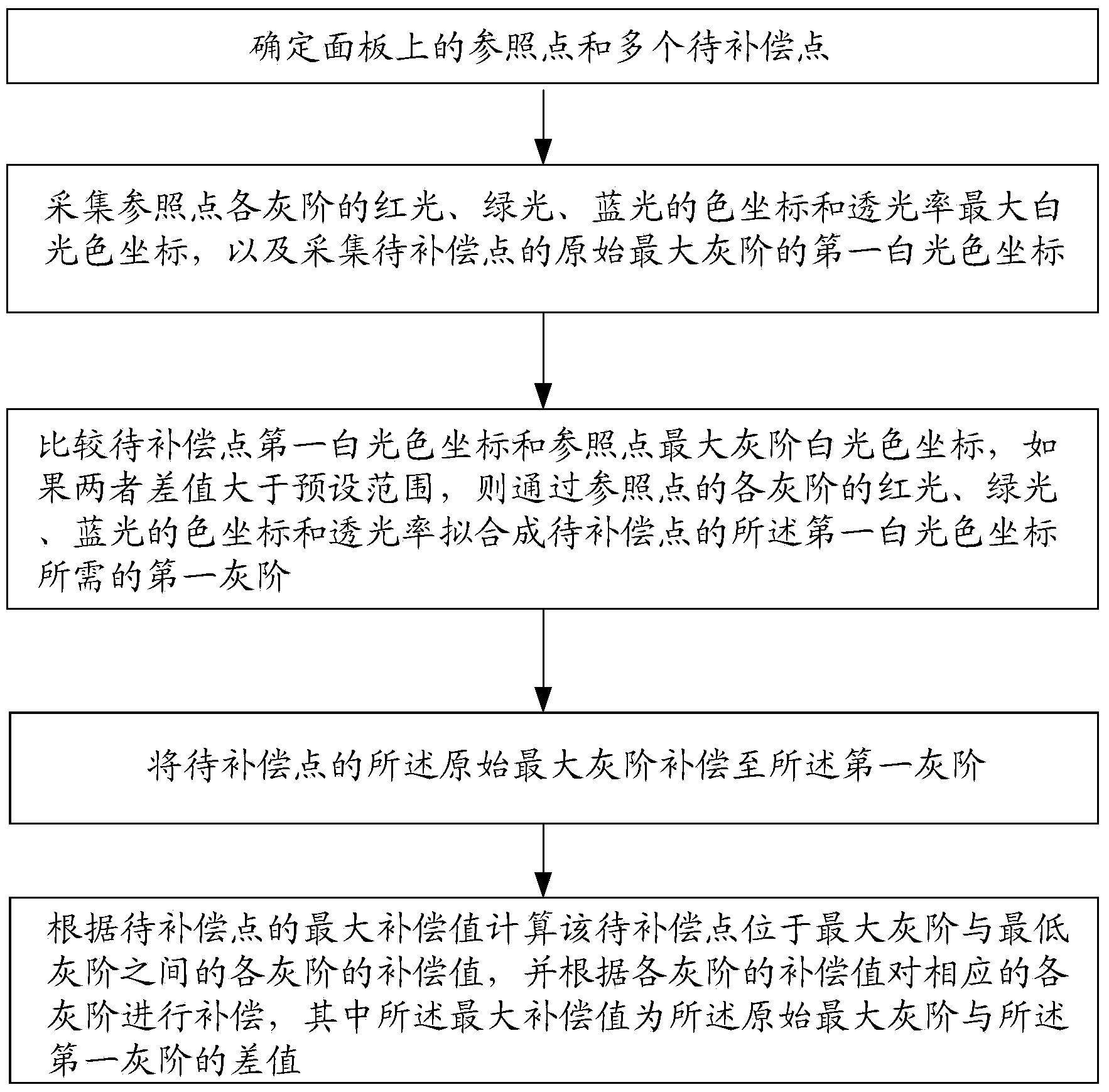
[0041] like figure 1 As shown, a method for improving LCD color cast includes the following steps:

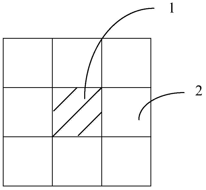
[0042] Determine the reference point on the panel and multiple points to be compensated;

[0043] Collect the color coordinates and light transmittance of red light, green light, and blue light of each gray scale of the reference point ...


PUM


Abstract

The invention relates to a method for improving color errors, a color error adjustment structure and a display device. The method for improving the color errors comprises the steps that a reference point and a plurality of points to be compensated on a panel are determined; color coordinates and light transmission rates of red light, green light and blue light of each gray scale of the reference point and color coordinates of white light of the maximum gray scale are collected, and color coordinates of first white light of the original maximum gray scale of the points to be compensated are collected; the color coordinates of the first white light are compared with the color coordinates of the while light of the maximum gray scale of the reference point, if a difference value between the color coordinates of the first white light and the color coordinates of the while light of the maximum gray scale of the reference point is larger than a preset range, a first gray scale needed by the color coordinates of the first white light is formed by fitting the color coordinates and the transmission rates of the red light, the green light and the blue light of each gray scale of the reference point; the original maximum gray scale of the points to be compensated is compensated to the first gray scale; compensation values of the points to be compensated of each gray scale located between the maximum gray scale and the minimum gray scale are calculated according to a maximum compensation value of the points to be compensated, each gray scale is compensated according to the compensation value of the gray scale, and the maximum compensation value is a difference value between the original maximum gray scale and the first gray scale.

Description

technical field [0001] The invention relates to the display field, in particular to a method for improving color shift, a color shift adjustment structure and a display device. Background technique [0002] At present, ordinary LCD (Liquid Crystal Display, liquid crystal display) products generally use side-type LED backlights, in which the white light emitted by the LED light bar is multi-wavelength mixed light, and the mixed light enters the light guide plate from the side of the light guide plate and guides the light guide plate. Diffuse in the center, and finally form a uniform surface light source. In this structure, due to the different absorption and dispersion capabilities of the light guide plate for visible light of different wavelengths, the uniformity of visible light of different wavelengths on the light guide plate is different, so the color coordinate uniformity of the white mixed light emitted by the light guide plate is poor. In addition, due to equipment a...

Claims


Application Information

Patent Timeline
Patent Type & Authority Applications(China)
IPC IPC(8): G09G3/36
Inventor 林丽锋占红明王永灿
Owner BOE TECH GRP CO LTD
Why Eureka
Try Eureka