

Magnetic latching direct current contactor
A DC contactor and magnetic holding technology, applied in electromagnetic relays, electromagnetic relay details, relays, etc., can solve the problems of complex assembly process, easy rust of permanent magnets, etc., and achieve short bounce time, simple assembly, and high strength. Effect
- Summary
- Abstract
- Description
- Claims
- Application Information
AI Technical Summary
Problems solved by technology
Method used
Image

Examples
Embodiment Construction
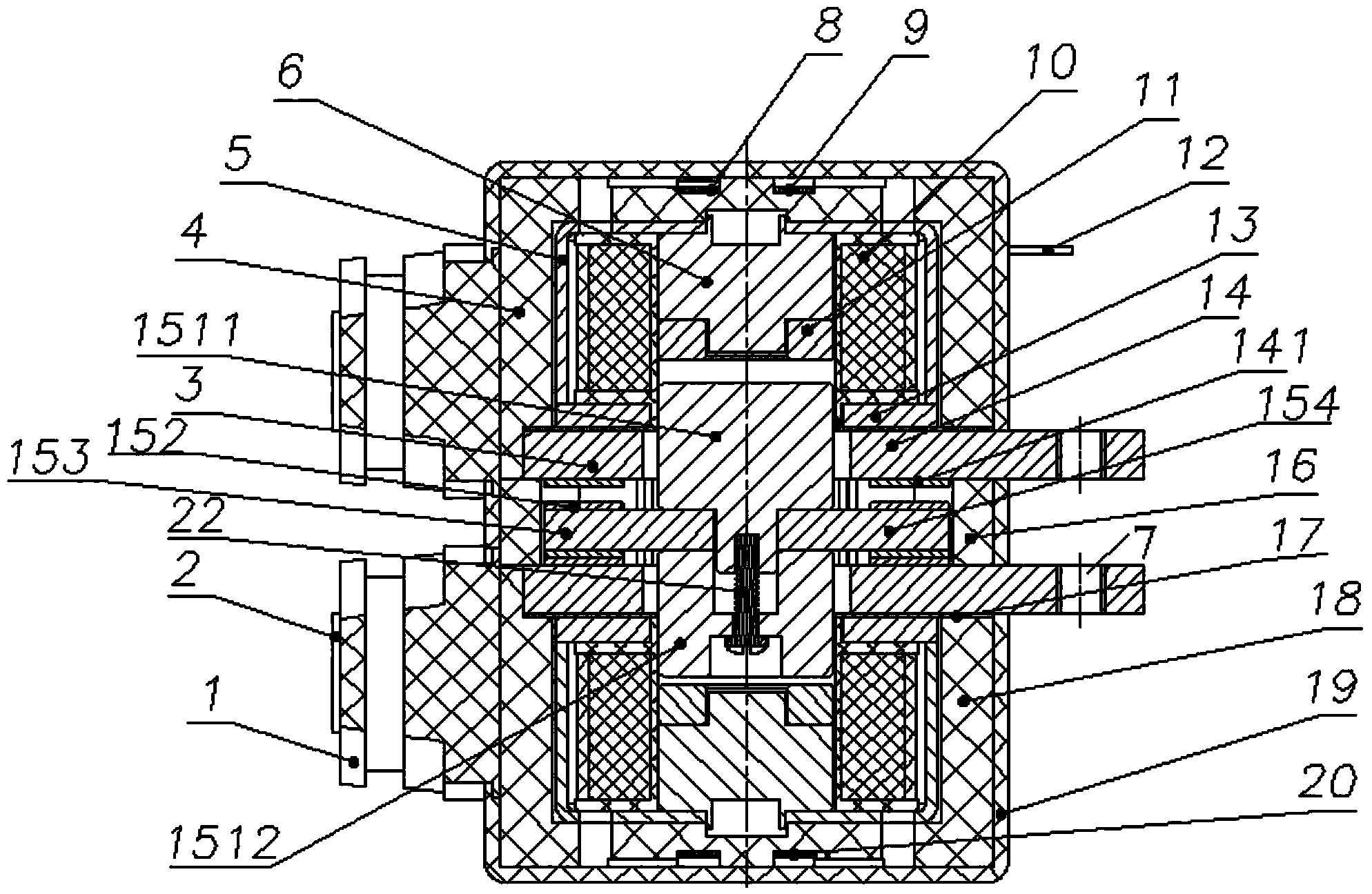
[0029] Such as Figure 1-Figure 3 The shown magnetic holding DC contactor includes a housing, and three sets of contact-electromagnetic units arranged in the housing. The contact-electromagnetic units include a contact system and control the contact system to break. Electromagnetic system for opening and closing.
[0030] In this embodiment, the contact system includes a static contact system and a moving contact system, the static contact system includes two static contact assemblies arranged opposite to each other up and down, the moving contact system includes a moving iron core, and A moving contact assembly that is integrated with the moving iron core. The moving contact assembly is located between the static contact assemblies, and when the moving iron core moves back and forth, the moving contact 152 on the moving contact assembly and the upper side Or the static contact on the static contact assembly on the lower side is connected.
[0031] The electromagnetic system...
PUM
 Abstract
Description
Claims
Application Information