Rotor, built-in permanent magnet motor and compressor

A permanent magnet motor, built-in technology, applied in synchronous machine parts, magnetic circuit rotating parts, magnetic circuit shape/style/structure, etc. Problems such as poor magnetic field distribution

Active Publication Date: 2015-01-21
DANFOSS (TIANJIN) CO LTD
View PDF2 Cites 12 Cited by
  • Summary
  • Abstract
  • Description
  • Claims
  • Application Information

AI Technical Summary

Problems solved by technology

[0004] However, the rotor structure of traditional interior permanent magnet motors often leads to poor air gap magnetic field dis...

Method used


Image

  • Rotor, built-in permanent magnet motor and compressor
  • Rotor, built-in permanent magnet motor and compressor
  • Rotor, built-in permanent magnet motor and compressor

Examples


Embodiment Construction

[0028] Through the following examples, combined with the attached Figure 1-7 , the technical solution of the present invention will be further specifically described. In the specification, the same or similar reference numerals designate the same or similar components. The following description of the embodiments of the present invention with reference to the accompanying drawings is intended to explain the general inventive concept of the present invention, but should not be construed as a limitation of the present invention.

[0029] The interior permanent magnet motor according to the embodiment of the present invention will be described below with reference to the accompanying drawings.

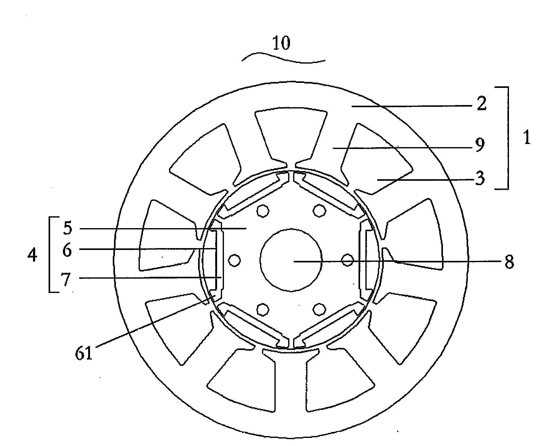
[0030] figure 1 A cross-sectional view of a conventional interior permanent magnet motor 10 is shown. The interior permanent magnet motor 10 comprises: a stator 1, a coil wound on the stator 1 (not in figure 1 shown in ) and a rotor 4 which is rotatably arranged in the stator 1 .

...


PUM


Abstract

The present invention provides a rotor, a built-in permanent magnet motor and a compressor. The rotor is used in the built-in permanent magnet motor and includes a rotor core; multiple permanent magnetsinstalled inside the rotor core at intervals; multiple air tanksarranged to be adjacent to the end portion fo the permanent magnet and close to the outer periphery of the rotor; multiple dents, each dent being arranged on the outer periphery of the rotor and making air gap flux density between the outer periphery of rotor and inner circumference of the stator of built-in permanent magnet motor being close to the sine curve.

Description

technical field [0001] The invention relates to the field of permanent magnet motors, in particular to a rotor configuration of an interior permanent magnet motor, an interior permanent magnet motor using the rotor and a related compressor. Background technique [0002] Generally, a permanent magnet motor such as a brushless DC motor has permanent magnets mounted on a rotor core to generate rotational driving force. Based on how permanent magnets are installed on the rotor core, permanent magnet motors are classified into surface-mounted permanent magnet motors and built-in permanent magnet motors. [0003] Typically, an interior permanent magnet motor has a plurality of permanent magnets mounted in the rotor core. An interior permanent magnet motor consists of a stator, coils wound around the stator, and a rotor. The rotor is rotatably arranged in the stator. [0004] However, the rotor structure of the traditional interior permanent magnet motor often leads to poor dist...

Claims


Application Information

Patent Timeline
IPC IPC(8): H02K1/27H02K21/02
Inventor 刘万振
Owner DANFOSS (TIANJIN) CO LTD
Why Eureka
Try Eureka