Air duct structure of special electronic dehumidifier for electrical equipment

An electrical equipment and dehumidifier technology, applied in the field of air duct structure, can solve the problems of reducing condensation, inability to dehumidify, unreasonable air duct design, etc., so as to reduce ambient temperature rise, reduce condensation surface temperature, and improve safe operation. sexual effect

Inactive Publication Date: 2015-01-21
叶秋诗 +1
View PDF5 Cites 1 Cited by
  • Summary
  • Abstract
  • Description
  • Claims
  • Application Information

AI Technical Summary

Problems solved by technology

The dehumidification effect of the electrical equipment inside the actual cabinet is not good. The electric heating actually increases the air flow and reduces the condensation to a certain extent, so it cannot dehumidify at all. , only local dehumidification in the cabinet
After opening the cabinet door, it is found that there is condensed water on the cabinet door or the electrical equipment at the position blocked by the electrical equipment or far away from the installation position of the conventional electronic dehumidifier, indicating that this dehumidification method cannot meet the requirements of the electrical equipment in the cabinet. Basic requirements for safe operation
The dehumidification of various indoor and outdoor electrical equipment cabinets adopts the method of installing electric heating in the cabinet with natural ventilation or forced ventilation, and sometimes the second, third and fourth guide wires around the electric heater are prematurely aged or burned , and because the air inside and outside the cabinet communicates, frequent heating and dehumidification not only has poor dehumidification effect, but also keeps high power consumption. The conventional electronic dehumidifier installed in the current terminal cabinet exists due to the compact design and installation of electrical equipment in the terminal cabinet. Without the installation position of the electronic dehumidifier, sometimes even if it can be installed in the terminal cabinet, the installation position affects the convenience of maintenance of the main equipment in the terminal cabinet. Installing a Conventional Electronic Dehumidifier

Method used


Image

  • Air duct structure of special electronic dehumidifier for electrical equipment
  • Air duct structure of special electronic dehumidifier for electrical equipment
  • Air duct structure of special electronic dehumidifier for electrical equipment

Examples


Embodiment Construction

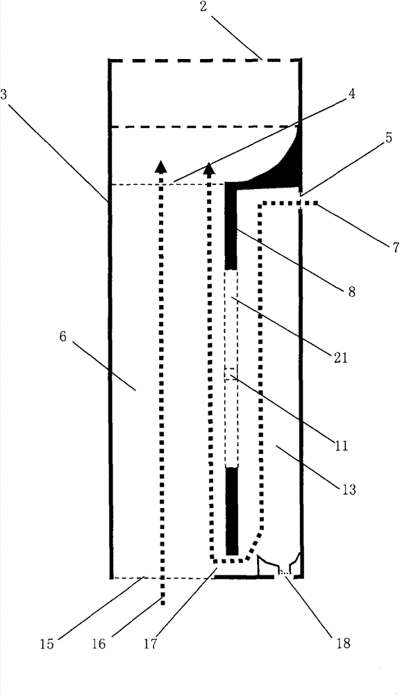
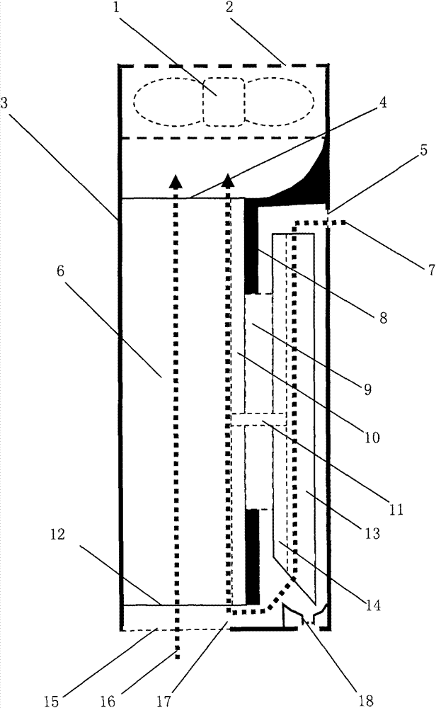
[0013] in figure 1 Shown is the internal air duct structure of the electronic dehumidifier dedicated for electrical equipment. The housing (3) of the dedicated electronic dehumidifier for electrical equipment has a cooling air outlet (2) a cooling air inlet (15) a humid air condensation air inlet ( 5) and the drain outlet of the condensate collection tank (18), the heat dissipation condensing channel is sealed in the housing (3) of the electronic dehumidifier for electrical equipment, and the flame retardant heat insulation board (8) is designed, and the heat dissipation condensate channel is sealed on the flame retardant heat insulation board ( 8) Separate the shell (3) of the electronic dehumidifier for electrical equipment into a heat dissipation channel (6) and a condensation channel (13) which are completely separated at the upper part, and the heat dissipation and condensation channel closes the upper part of the flame-retardant heat insulation board (8) and the electrical ...


PUM


Abstract

A shell of a special electronic dehumidifier for electrical equipment is provided with a heat dissipation air outlet, a cooling air inlet of a heat dissipation channel, a wet air condensation air inlet, and a water outlet of a condensed water collection tank. A heat dissipation and condensation channel closing flame-retardant heat insulation plate is designed to divide the inside of the shell of the special electronic dehumidifier for electrical equipment into a heat dissipation channel and a condensation channel of which the upper parts are completely separated. A condensation dry air outlet of the condensation channel is reserved between the lower part of the heat dissipation and condensation channel closing flame-retardant heat insulation plate and the bottom of the shell of the special electronic dehumidifier for electrical equipment. A cooling electronic fan pumps hot air out of the heat dissipation channel, and cooling air quickly produces negative pressure at the condensation dry air outlet through the heat dissipation channel, so that wet air is condensed, dehumidified and dried through the condensation channel via the wet air condensation air inlet, and the condensed, dehumidified and dried cold dry air is attracted to flow to the condensation dry air outlet, and flows on the surface of the heat dissipation strip side of a rectangular aluminum heat dissipation plate to take away the heat of a rectangular aluminum heat dissipation plate substrate. The mode of linear arrangement of the cooling air duct reduces the cooling air resistance and improves the efficiency of dehumidification.

Description

Technical field [0001] The invention relates to an air duct structure of a special electronic dehumidifier for electrical equipment installed in various electrical equipment cabinets. In particular, the electronic dehumidifier for electrical equipment is installed in the cabinet of electrical equipment that needs dehumidification, which can meet the dehumidification of electrical equipment and adjust the ambient temperature in the cabinet to a certain extent. The power consumption of the electronic dehumidifier for electrical equipment is higher than that of the current power system. The electronic dehumidifier installed in the terminal box of the same power to be promoted and tried has low power consumption, and the dedicated electronic dehumidifier air duct structure for electrical equipment has high dehumidification efficiency. The electronic dehumidifier dedicated for electrical equipment is flat and miniaturized, and the series of the same air duct structure The product mee...

Claims


Application Information

Patent Timeline
Patent Type & Authority Applications(China)
IPC IPC(8): H05K7/20
Inventor 叶秋诗
Owner 叶秋诗
Why Eureka
Try Eureka