

Wearable fetus education bellyband system with fetus sound monitoring, fetus movement detection and fetus movement trajectory induction functions
A wearable, prenatal education technology, applied in the field of biomedical electronic engineering, can solve the problems of inconvenient use and high price of equipment, and achieve the effect of reducing neck wrapping, easy wearing, prevention or neck wrapping
- Summary
- Abstract
- Description
- Claims
- Application Information
AI Technical Summary
Problems solved by technology
Method used
Image

Examples
Embodiment Construction
[0033] In order to make the object, technical solution and advantages of the present invention clearer, the present invention will be further described in detail below in conjunction with the accompanying drawings and embodiments. It should be understood that the specific embodiments described here are only used to explain the present invention, not to limit the present invention.
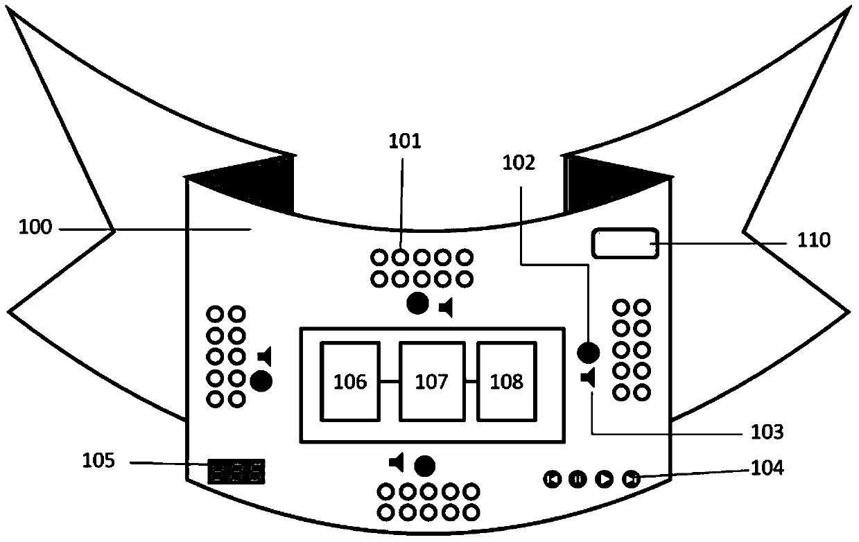
[0034] figure 1 It is a structural schematic diagram of the abdominal belt system of a preferred embodiment of the present invention. Please refer to figure 1, the present invention is a wearable fetal education abdominal belt system with the functions of fetal sound monitoring, fetal movement detection and fetal movement trajectory induction. Or straps and other ways to connect, convenient for pregnant women to wear. The flexible substrate (100) is provided with a pickup array (102), a sound collection and detection module (106) connected to the pickup array (102), a voice integration module (1...
PUM
 Abstract
Description
Claims
Application Information