
Reaction kettle with rotating shaft with adjustable length

A technology of reaction kettle and rotating shaft, applied in the field of reaction kettle, can solve the problems of insufficient rotating shaft, short falling distance, sufficient material stirring, etc.

Inactive Publication Date: 2015-01-28
SICHUAN FUDI NEW ENERGY
View PDF6 Cites 0 Cited by
  • Summary
  • Abstract
  • Description
  • Claims
  • Application Information

AI Technical Summary

Problems solved by technology

[0003] In order to solve the shortcomings of the existing reactors such as the short falling distance and the insufficient length of the rotating shaft to fully stir the materials at the bottom of the reactor body, the present invention provides a reactor with an adjustable rotating shaft length.

Method used


Image

  • Reaction kettle with rotating shaft with adjustable length
  • Reaction kettle with rotating shaft with adjustable length

Examples


Embodiment 1

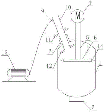
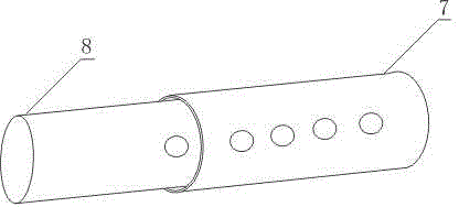
[0017] Such as figure 1 , figure 2 As shown, the reaction kettle with adjustable shaft length includes a kettle body 1, a feed inlet 2 arranged at the upper end of the kettle body 1, and a discharge port 3 arranged at the lower end of the kettle body 1. The kettle body 1 is a cavity structure, It also includes a motor A4 installed on the upper end of the kettle body 1, a rotating shaft 5 connected with the motor A4, the other end of the rotating shaft 5 is inserted into the cavity structure of the kettle body 1, and a rotating piece 6 connected with the rotating shaft 5; The rotating shaft 5 is a telescopic rotating shaft; wherein the rotating shaft 5 includes an outer cylinder 7, an inner cylinder 8 slidingly arranged in the outer cylinder 7, and uniform circular holes are opened on the outer cylinder 7 and the inner cylinder 8, The outer cylinder body 7 and the inner cylinder body 8 are fixed by bolts penetrating the outer cylinder body 7 and the inner cylinder body 8 at t...

Embodiment 2

[0020] On the basis of Embodiment 1, this embodiment also includes an adjustable feeding device 9 installed on the feeding port 2 .

[0021] In this embodiment, the feeding device 9 can adjust the falling distance of the material according to the properties of the material, so as to avoid the phenomenon of material agglomeration due to the short falling distance of the material.

Embodiment 3

[0023] In this embodiment, on the basis of Embodiment 1 or Embodiment 2, the feed device 9 includes a feed pipe 10, an upper plate 11 installed on the feed pipe 10, and a lower plate 12 installed at the end of the feed pipe 10. , also includes a motor B13 connected to the feeding device 9 .

[0024] In this embodiment, the feeding pipe 10 can be moved along the axial direction of the feeding port 2 through the control of the motor B13. The setting of the lower plate 12 prevents the feeding pipe 10 from slipping out of the kettle body 1, and the setting of the upper plate 11 avoids Feed pipe 10 is all divided into still body 1.


PUM


Abstract

The invention discloses a reaction kettle with a rotating shaft with adjustable length. The reaction kettle comprises a kettle body, a feeding hole formed in the upper end of the kettle body and a discharge hole formed in the lower end of the kettle body, as well as a motor arranged at the upper end of the kettle body, the rotating shaft connected with the motor, and a rotating plate connected with the rotating shaft, wherein the kettle body is of a cavity structure; the other end of the rotating shaft is inserted into the cavity structure of the kettle body; the rotating shaft is telescopic and comprises an outer cylinder and an inner cylinder arranged in the outer cylinder in a sliding manner, and both the outer cylinder and the inner cylinder are provided with uniform circular holes and fixed through bolts simultaneously penetrating through the outer cylinder and the inner cylinder. The inner cylinder is arranged in the outer cylinder in the sliding manner, so that the rotating shaft can stretch as required, which ensures that materials in the kettle body can be sufficiently stirred by the rotating plate. According to a feeding device, the falling distance of the materials can be adjusted according to the properties of the materials, so that a phenomenon of material agglomeration due to short falling distance of the materials is avoided.

Description

technical field [0001] The invention relates to a reaction kettle, in particular to a reaction kettle with an adjustable rotating shaft length. Background technique [0002] The existing reaction kettle is fed through the feed inlet fixed on the reactor, but often because the position of the feed inlet is fixed, the falling distance of the material is shorter, and the falling distance of the material is shorter, so that the material falls and immediately enters the reaction state. . Moreover, the short distance of falling of the material is also easy to cause serious agglomeration of the material, which will cause uneven reaction and ultimately affect the quality of the reaction. Furthermore, the existing reactor has only one stirring device, and the stirring device often cannot fully stir the materials at the bottom of the kettle body because the rotating shaft is not long enough. Contents of the invention [0003] In order to solve the shortcomings of the existing reac...

Claims


Application Information

Patent Timeline
IPC IPC(8): B01J19/18B01J4/00
CPCB01J19/18B01J4/001B01J19/0066B01J2219/185
Inventor 王鸿徐竹
Owner SICHUAN FUDI NEW ENERGY
Learn More