
LED (light emitting diode) lamp circuit board welding frame

A technology for LED lamps and circuit boards, applied in the field of welding racks, can solve the problems of easy circuit board shaking, welding errors, etc., and achieve the effects of avoiding unstable fixation, reducing welding errors, and reducing natural temperature recovery time.

Inactive Publication Date: 2015-01-28
SUZHOU CHENGTENG ELECTRONICS TECH
View PDF8 Cites 1 Cited by
  • Summary
  • Abstract
  • Description
  • Claims
  • Application Information

AI Technical Summary

Problems solved by technology

[0003] The purpose of the present invention is to provide a welding frame for welding LED circuit boards. The circuit board is fixed by the circuit board clamp, and the circuit is observed through a magnifying glass, which facilitates the welding of the circuit and solves the problem that the circuit board is easy to shake when welding the circuit board. And the problem of welding errors caused by small circuits

Method used


Image

  • LED (light emitting diode) lamp circuit board welding frame

Examples


Embodiment Construction

[0011] In order to deepen the understanding of the present invention, the present invention will be described in further detail below with reference to the embodiments, which are only used to explain the present invention and do not constitute a limitation on the protection scope of the present invention.

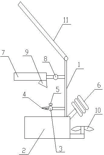
[0012] like figure 1 As shown, this embodiment provides a LED lamp circuit board welding frame, including a main body 1, a base 2 is provided at the bottom of the main body 1, and a circuit board clip is provided at the bottom of the main body 1, and the circuit board clip includes a beam 3 and clip 4, the clip 4 is arranged at both ends of the beam 3, the beam 3 is provided with tightening bolts 5 to control the length of the beam 3 left and right, the lower part of the main body 1 and the side of the circuit board clip are provided with a welding torch The bracket 6 is provided with a magnifying glass 7 on the upper side of the main body 1 . The magnifying glass 7 is con...


PUM


Abstract

The invention provides an LED (light emitting diode) lamp circuit board welding frame. The LED lamp circuit board welding frame comprises a main body, wherein a base is arranged on the bottom end of the main body, a circuit board clamp is arranged on the lower part of the main body, the circuit board clamp comprises a crossbeam and a clamp, the clamp is arranged on two ends of the crossbeam, the crossbeam is provided with a tightening bolt which is used for controlling the length of the crossbeam, a weld gun support is arranged on one side of the circuit board clamp on the lower part of the main body, and a magnifying lens is arranged on the upper side of the main body. The circuit board is fixed by the circuit board clamp which is arranged on the main body, so that the instability in fixation of the circuit board caused by the reason that the circuit board is fixed by one hand of an operator while the weld gun is held by the other hand of the operator can be avoided; moreover, by adopting the magnifying lens, the heading direction of the circuit is convenient to observe when in welding, and errors in welding can be reduced; by adopting a small-sized fan to rapidly cool the weld gun which is not in use, the time for naturally cooling the weld gun can be reduced, the working efficiency is improved, and defective goods can be reduced.

Description

technical field [0001] The invention relates to the field of manufacturing LED lamps, in particular to a welding frame for welding LED circuit boards. Background technique [0002] At present, when welding LED circuit boards, because the circuit boards are small and the circuits are small, mistakes often occur during welding, resulting in waste of circuit boards and electrical components. When welding, one hand is used to fix the circuit board and the other Holding the welding torch in one hand for welding, it is easy to shake the circuit board when it is still and move, causing mistakes. Present welding support can only be used for placing welding torch, and there is no way to solve the above problems. Therefore, it is particularly important to solve the problem that the circuit board is easy to shake and the welding errors caused by the small circuit when welding the circuit board. Contents of the invention [0003] The purpose of the present invention is to provide a ...

Claims


Application Information

Patent Timeline
Patent Type & Authority Applications(China)
IPC IPC(8): B23K31/02B23K37/00B23K37/02B23K37/04B23K101/36
CPCB23K3/08B23K3/027B23K3/085B23K3/087B23K2101/36
Inventor 顾燕萍
Owner SUZHOU CHENGTENG ELECTRONICS TECH
Learn More