Water gap cutting structure of automobile injection mold

An injection mold and nozzle technology, applied in the field of injection molding, can solve problems such as protrusion, incomplete connection of connecting parts, and inability to ensure the stability of injection molding, and achieve the effect of facilitating demoulding and improving accuracy.

Inactive Publication Date: 2021-06-29
杨向东
View PDF0 Cites 0 Cited by
  • Summary
  • Abstract
  • Description
  • Claims
  • Application Information

AI Technical Summary

Problems solved by technology

[0004] Aiming at the deficiencies of the prior art, the present invention provides a nozzle structure of an automobile injection mold, which solves the problem that the elasticity of the product may lead to displacement during the downward movement of the cutter, and it cannot be guaranteed under unstable conditions. The stability of the injection molding will cause the nozzle part to protrude, and if the cut section is too flat, it will also affect the later use, resulting in incomplete connection with the connector

Method used


Image

  • Water gap cutting structure of automobile injection mold
  • Water gap cutting structure of automobile injection mold
  • Water gap cutting structure of automobile injection mold

Examples


Embodiment 1

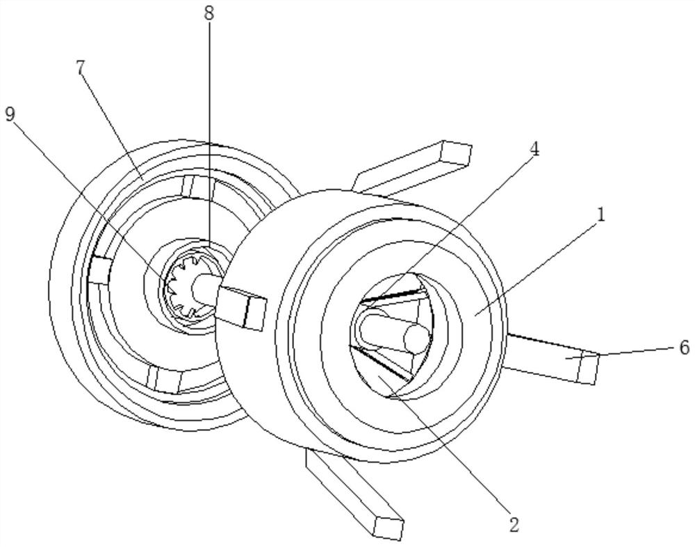
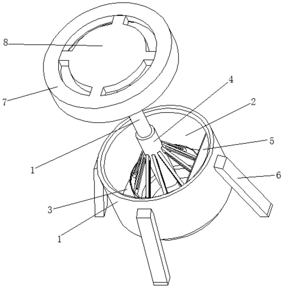
[0033] see Figure 1-2 , the present invention provides a technical solution: a nozzle structure of an automobile injection mold, including a workbench 1, the outer surface of the workbench 1 is provided with a circular through groove 2, and the inner surface of the circular through groove 2 is fixedly connected with a round table 3. The top of the round table 3 is provided with a connecting mechanism 4, the inner surface of the circular through groove 2 is located on the side close to the round table 3 and is fixedly connected with the organic case 5, and the outer surface of the workbench 1 is evenly rotated and connected with supporting legs 6, the supporting legs The inner surface of 6 is provided with a lengthening mechanism 10, the top of the workbench 1 is movably connected with a pressing disk 7, the outer surface of the pressing disk 7 is provided with a connecting groove, and the inner surface of the connecting groove is movably connected with a fixed disk 8 through a...

Embodiment 2

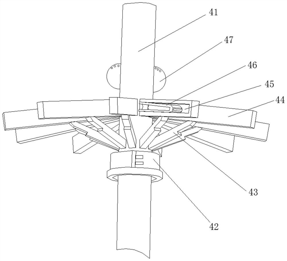
[0037] see Figure 3-5 , the present invention provides a technical solution: the connection mechanism 4 includes a tubular fixed casing 41, the outer surface of the tubular fixed casing 41 is movably connected with the outer surface of the pressing plate 7, and the outer surface of the tubular fixed casing 41 is fixed and located near the working One side of the platform 1 is fixedly connected with a connecting ring 42 , and the outer surface of the connecting ring 42 is movably connected with the outer surface of the tubular fixed casing 41 through buckles. Before the workpiece to be processed is conveyed, the fixed position of the connecting ring 42 can be adjusted, and the support position of the grab bar 44 can be adjusted. When the workpiece is small, it can also be accurately sent to the corresponding processing position. The outer surface of the tubular fixed sleeve 41 The surface is uniformly rotated and connected with a telescopic rod 43, and the top of the telescopi...

Embodiment 3

[0045] see Image 6 , the present invention provides a technical solution:

[0046] The pressing mechanism 9 includes an extrusion box 91, the outer surface of the extrusion box 91 is fixedly connected with the inner surface of the pressing plate 7, the inner surface of the extrusion box 91 is provided with a dark groove 97, and the inner surface of the dark groove 97 is fixedly connected with a The spring sheet 98, the inner surface of the extrusion box 91 is connected with the pressing tool 92 through the rotation of the spring shaft, and the top of the pressing tool 92 is provided with a nozzle groove 93, and the inner surface of the nozzle groove 93 is movable with the outer surface of the tubular fixed casing 41. Connection, the outer surface of the pressing tool 92 is fixedly connected with the fan piece 94, the outer surface of the fan piece 94 is uniformly fixedly connected with the connecting piece, and the outer surface of the connecting piece is movably connected wi...


PUM


Abstract

The invention discloses a water gap cutting structure of an automobile injection mold, and relates to the technical field of injection molding. The water gap cutting structure of the automobile injection mold comprises a workbench, a circular through groove is formed in the outer surface of the workbench, a circular truncated cone is fixedly connected to the inner surface of the circular through groove, a connecting mechanism is arranged at the top of the circular truncated cone, a case is fixedly connected to the side, close to the circular truncated cone, of the inner surface of the circular through groove, supporting legs are evenly and rotatably connected to the outer surface of the workbench, and the top of the workbench is movably connected with a press-fit disc. A press-fit mechanism, the connecting mechanism and other components are additionally arranged in the injection mold and used in cooperation, so that on one hand, the machining accuracy of the injection mold is improved; and on the other hand, when the injection mold is not stably supported, the injection mold can be held by hand to work, under the conditions of instability and other special conditions, the stability during injection molding is guaranteed at the first time, and when elastic materials expand with heat and contract with cold, the elastic materials can be accurately machined.

Description

technical field [0001] The invention relates to the technical field of injection molding, in particular to a nozzle structure of an automobile injection mold. Background technique [0002] Injection molding is a method of producing shapes for industrial products. Products usually use rubber injection molding and plastic injection molding. Injection molding can also be divided into injection molding molding method and die casting method. Injection molding machine (referred to as injection machine or injection molding machine) is the main molding equipment for making thermoplastic or thermosetting materials into various shapes of plastic products using plastic molding molds. Injection molding is realized through injection molding machines and molds. [0003] The material of existing automotive injection molding products has a certain degree of elasticity. When the nozzle of the workpiece is cut, it is usually cut with a cutter. The elasticity of the product itself may cause ...

Claims


Application Information

Patent Timeline
Patent Type & Authority Applications(China)
IPC IPC(8): B29C45/38B29C45/43
CPCB29C45/38B29C45/43
Inventor 杨向东
Owner 杨向东
Why Eureka
Try Eureka