
Laminate drop prevention mechanism for PCB (Printed circuit board) laminate trolley

A technology of pressing plate and transfer table, which is applied in the direction of transporting passenger cars, railway car body parts, cargo supporting/fastening parts, etc., can solve problems such as falling of pressing plates, and achieve the effect of preventing the falling of pressing plates

Inactive Publication Date: 2015-01-28
竞陆电子(昆山)有限公司
View PDF0 Cites 0 Cited by
  • Summary
  • Abstract
  • Description
  • Claims
  • Application Information

AI Technical Summary

Problems solved by technology

However, even if baffles are installed on the left and right sides of the trolley, when the manual operation is unskilled or improper, the pressure plate may still fall due to the instability of the trolley's running speed and inertial force.
In order to completely eliminate the scrap loss caused by the falling of the pressed plywood and the work-related accidents that may be caused by the falling of the plywood, this technical defect that may affect the yield and the safety hazard that may cause employee injuries must be resolved.

Method used


Image

  • Laminate drop prevention mechanism for PCB (Printed circuit board) laminate trolley
  • Laminate drop prevention mechanism for PCB (Printed circuit board) laminate trolley

Examples


Embodiment 1

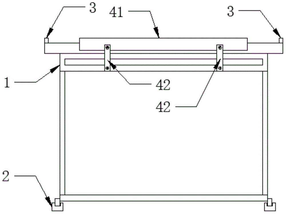
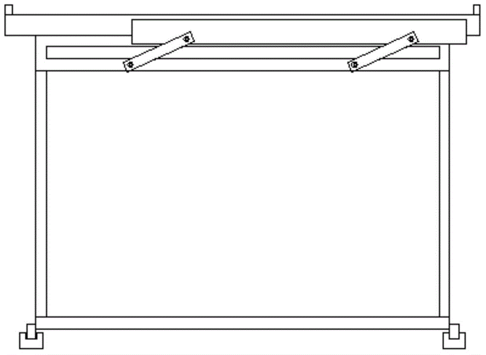
[0012] Embodiment 1: An anti-dropping mechanism of a PCB press-fitting plate transmission trolley, the transmission trolley 1 runs along the track 2, and the trolley has left and right sides parallel to the direction of the track and front and rear ends perpendicular to the direction of the track , the left and right sides of the trolley are all provided with side baffles 3 higher than the table, and the front and rear ends of the trolley are all provided with movable baffle mechanisms, and the movable baffle mechanisms are: the The front and rear ends of the trolley are all equipped with a movable frame, and the movable frame is formed by connecting the upper beam 41 and two vertical bars 42. The two vertical bars are arranged in parallel, and the lower ends of the two vertical bars are all fixed on the trolley. The upper end is connected to the upper beam, and the connection between the upper beam and the vertical bar is connected by bolts and nuts. When the vertical bar and ...

Embodiment 2

[0013] Embodiment 2: As a modification of Embodiment 1, an end baffle may also be provided, the vertical bar and the upper beam are all lower than the table, and the upper beam is fixed with an end baffle, when the vertical bar and the upper beam form a vertical State, end baffle is higher than table top, and end baffle can be lower than table top when vertical bar and upper crossbeam constitute non-perpendicular state, the size of movable frame (upper crossbeam and vertical bar) in this embodiment (especially Left and right dimension) can be designed smaller than that in embodiment 1, and the movable frame does not serve as the baffle function but only as a mechanism for the height of the lifting end baffle.


PUM


Abstract

The invention discloses a laminate drop prevention mechanism for a PCB (Printed circuit board) laminate trolley. Both left and right of the trolley are provided with side retaining plates higher than a trolley-top; both the front and rear ends of the trolley are provided with moving retaining plate mechanisms; the moving retaining plate mechanism comprise moving frames mounted at front and rear ends of the trolley, each moving frame is formed by connecting an upper cross beam and two vertical rods which are parallel, the lower ends of the vertical rods are all fixed on the trolley, the upper ends of the vertical rods are connected with the upper cross beams, and the upper beams and the vertical rods are connected through bolts and nuts. The upper cross beams and the vertical rods can be adjusted in a vertical state, the upper cross beams form retaining plates preventing laminate drop, dropping of laminates can be fully avoided, abandonment loss caused by laminate drop is fully avoided, and possible industrial accidents caused by laminate drop are fully avoided. When prevention is not required, the vertical rods and the upper cross beams can be adjusted in a non-vertical state, the upper cross beams are lower than the trolley-top.

Description

technical field [0001] The invention belongs to the field of equipment for manufacturing printed circuit boards, and in particular relates to a trolley structure for back and forth transporting PCB laminated boards. Background technique [0002] In the prior art, the PCB laminated board needs to be transported back and forth on the transfer trolley, and the trolley is transported back and forth along the track. Generally, in order to prevent the plywood from falling off the trolley, baffles are provided on the left and right sides of the trolley (that is, parallel to the track). Due to the existence of the above-mentioned baffles on the left and right sides, the trolley generally There will be no board drop. However, even if baffles are provided on the left and right sides of the trolley, when the manual operation is unskilled or improper, the pressure plate may still fall due to the instability of the trolley's running speed and inertial force. In order to completely elim...

Claims


Application Information

Patent Timeline
IPC IPC(8): B61D15/00
CPCB61D15/00B61D45/00
Inventor 李泽清
Owner 竞陆电子(昆山)有限公司
Learn More