A bucket type grain throwing machine

A grain throwing machine and bucket type technology, which is applied in the field of grain throwing devices, can solve the problems of unstable grain throwing trajectory, large volume and high noise of the grain thrower, and achieve the effects of long service life, small size and high efficiency.

Active Publication Date: 2017-02-15
HENAN JINMING AUTOMATION EQUIP
View PDF1 Cites 2 Cited by
  • Summary
  • Abstract
  • Description
  • Claims
  • Application Information

AI Technical Summary

Problems solved by technology

[0004] The purpose of the present invention is to provide a bucket-type grain throwing machine to solve the problems of large volume, unstable grain throwing track and loud noise

Method used


Image

  • A bucket type grain throwing machine
  • A bucket type grain throwing machine
  • A bucket type grain throwing machine

Examples


Embodiment Construction

[0024] The present invention will be described in further detail below through specific embodiments in conjunction with the accompanying drawings.

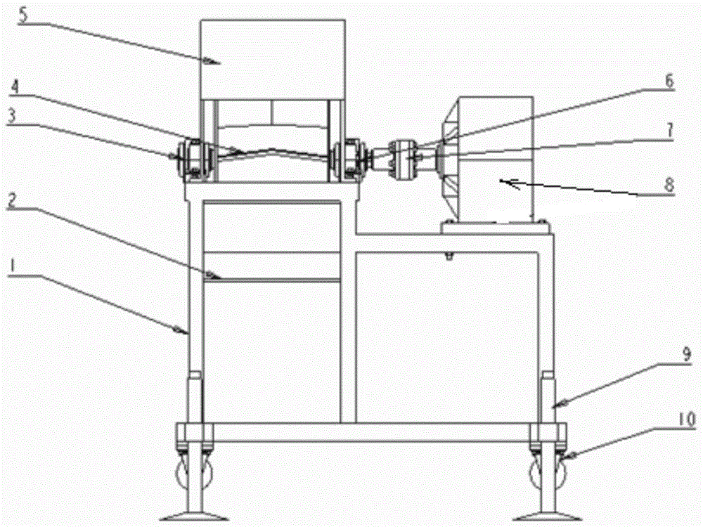
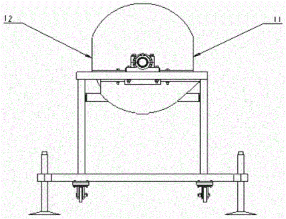
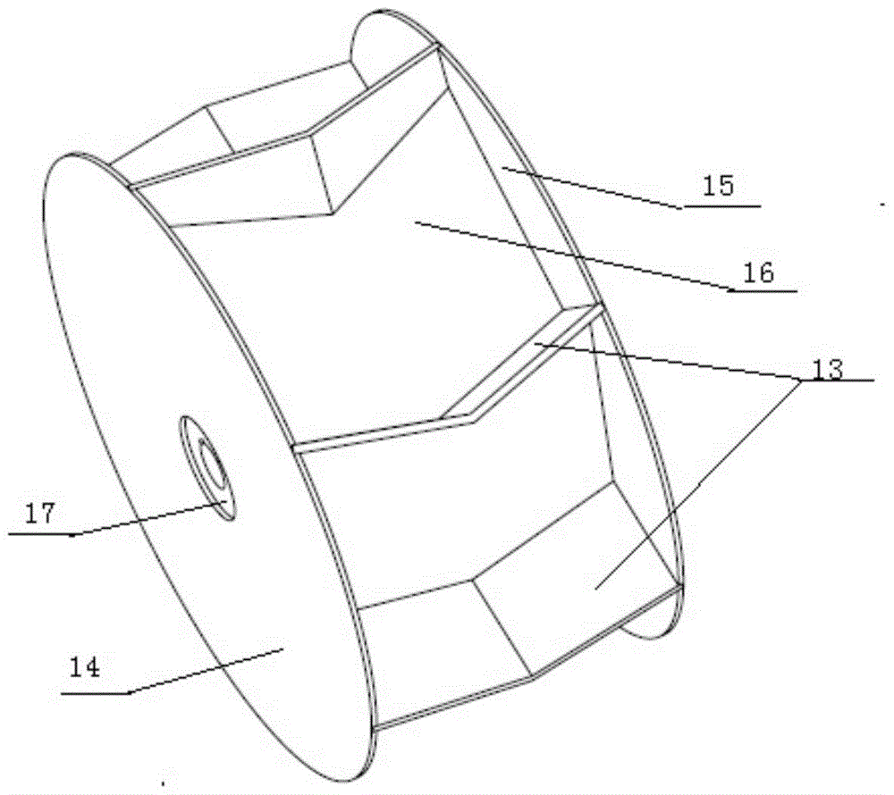
[0025] Considering the problems of large volume, high noise and unstable grain throwing trajectory of the currently commonly used grain throwing machines, the present invention provides a bucket-type grain throwing machine. The grain throwing machine includes: a frame, a grain throwing cover, a throwing motor, and an impeller; the upper part of the frame has the grain throwing cover, the impeller is placed in the beam throwing cover, Bearing seats stand respectively on the frame, the central shaft of the impeller is connected with the output shaft of the throwing motor through a coupling, and the central shaft, the coupling and the output shaft are the same shaft; the grain throwing hood is provided with an inlet and an outlet, and the blades of the impeller are curved plates.

[0026] Generally, the blades of the impeller adopt ...


PUM


Abstract

The invention relates to a winnowing pan type grain throwing machine. The winnowing pan type grain throwing machine comprises a frame, a grain throwing hood, a throwing motor and an impeller. The impeller is arranged in the grain throwing hood which is arranged on the upper portion of the frame, bearing seats at two ends of the impeller are arranged on the frame respectively, a center shaft of the impeller is connected with an output shaft of the throwing motor through a coupler, and the center shaft, the coupler and the output shaft are coaxial. The grain throwing hood is provided with a feeding port and a discharging port, and blades of the impeller are bent plates. The winnowing pan type grain throwing machine has the advantages of small size, stability of grain throwing paths, low noise, detachability of parts, convenience in installation and maintenance, low cost and flexibility in use.

Description

technical field [0001] The invention relates to a grain throwing device, in particular to a bucket type grain throwing machine. Background technique [0002] In bulk grain turnover storage, it is necessary to realize the transportation and transfer of grain. Existing grain conveying machinery has multiple forms, such as belt conveyors, buried scraper conveyors, bucket elevators, screw conveyors, vibrating conveyors and grain throwers. The use of ordinary conveying machinery can meet the actual requirements to a certain extent, but it is inevitable that there will be various defects and conditions. For example, the conveying distance of the belt conveyor is limited by its own length, the volume is large, the weight is large, and the output is low. Such as utility model patent CN203529308U provides remote delivery grain throwing machine, the lower end of the upper frame is provided with the lower frame, the lower end of the lower frame is provided with the front support, the ...

Claims


Application Information

Patent Timeline
Patent Type & Authority Patents(China)
IPC IPC(8): B65G31/02A01F25/18
Inventor 王明旭李永祥任凯轩翟中阳曹宪周晏丽
Owner HENAN JINMING AUTOMATION EQUIP
Why Eureka
Try Eureka