Stamping device for shells of mini-tillers

The technology of a stamping device and a micro-tiller is applied in the field of sheet metal stamping, which can solve the problems of time-consuming and laborious, affecting the aesthetics of the shell, and achieve the effect of easy demoulding

Pending Publication Date: 2018-11-02
重庆伦瑞风传动科技有限公司
View PDF0 Cites 2 Cited by
  • Summary
  • Abstract
  • Description
  • Claims
  • Application Information

AI Technical Summary

Problems solved by technology

[0003] When stamping the plate, some impurities or iron filings usually fall off the last processed plate in the cavity of the die. In this case, the plate is stamped, and the impurities or iron filings will make the formed shell The formation of pits will affect the aesthetics of the shell; therefore, when stamping the plate, the cavity of the die must be cleaned first, but at present, it is mainly cleaned manually, which is time-consuming and laborious

Method used


Image

  • Stamping device for shells of mini-tillers
  • Stamping device for shells of mini-tillers
  • Stamping device for shells of mini-tillers

Examples


Embodiment Construction

[0024] The present invention will be described in further detail below by means of specific embodiments:

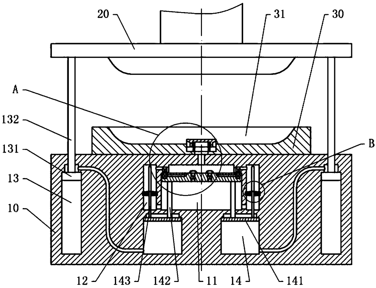
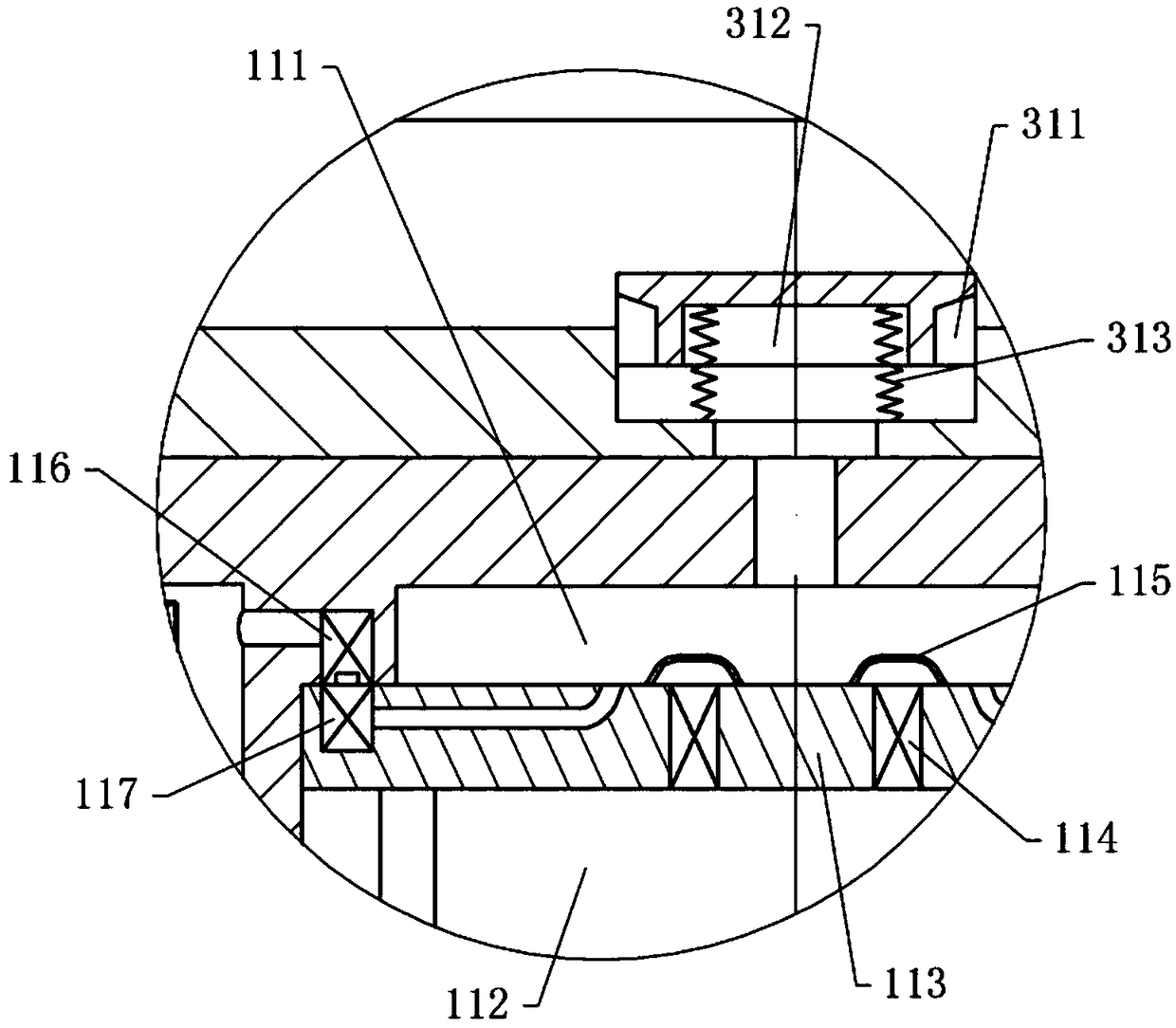
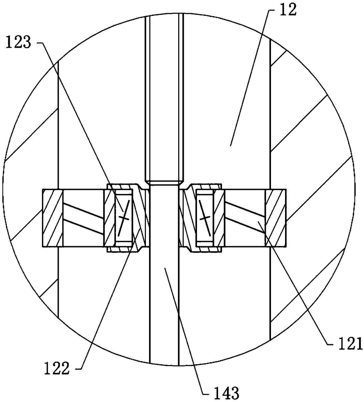
[0025] The reference signs in the accompanying drawings include: seat body 10, liquid chamber 11, first chamber 111, second chamber 112, first piston plate 113, one-way valve 114, filter screen 115, first quick connector 116, second Two quick connectors 117, diversion channel 12, pump wheel 121, drive ring 122, one-way bearing 123, first oil chamber 13, piston 131, connecting rod 132, second oil chamber 14, second piston plate 141, push rod 142, drive rod 143, punch 20, die 30, launder 311, blocking block 312, stage clip 313.

[0026] The embodiment is basically as figure 1 , figure 2 and image 3 Shown:

[0027] The stamping device of the tiller housing in this embodiment includes a base body 10, a die 30 fixed on the base body 10, a punch 20 which is arranged above the die 30 and can cooperate with the die 30, and drives the punch 20 up and down. A moving stamping...


PUM


Abstract

The application relates to the field of plate stamping, and particularly discloses a stamping device for shells of mini-tillers, which comprises a base, a female die, a male die, and a stamping machine, the female die is fixed to the base, the interior of the base is provided with a liquid cavity and diversion passages, a first piston plate is arranged in the liquid cavity, the first piston platedivides the liquid cavity into a first cavity and a second cavity, the interior of the female die is provided with a liquid inlet passage which is communicated with the die cavity, the liquid inlet passage is communicated with the first cavity, and the sidewall of the first cavity is provided with limit ribs; each limit rib is provided with a first quick connector which is connected to one end ofthe diversion passage, the other ends of the diversion passages are communicated with the second cavity, the first piston plate is provided with check valves and second quick connectors connected to the first quick connectors; the base is provided with a first oil cavity and a second oil cavity, a piston is arranged in the first oil cavity, a second piston plate is arranged in the second oil cavity, the upper end of the first oil cavity is communicated with the second oil cavity, and when moving upward, the male die can drive the second piston plate and the first piston plate to simultaneouslymove upwards; and water in the liquid cavity can get into the die cavity to flush the die cavity.

Description

technical field [0001] The invention relates to the technical field of plate punching, in particular to a punching device for a micro tillage machine shell. Background technique [0002] At present, when manufacturing a car, it is necessary to stamp the car shell to meet the installation requirements of the car. When stamping the car shell, a large stamping machine is usually used to stamp the car shell. However, due to the different stamping shapes, it is necessary to replace the die of the stamping machine and then stamp different shapes. Stamping processing is by means of conventional or The power of special stamping equipment makes the sheet material directly subjected to deformation force and deformed in the mold, so as to obtain the production technology of product parts with certain shape, size and performance. Sheet metal, mold and equipment are the three elements of stamping processing. Stamping is a metal cold deformation processing method. Therefore, it is call...

Claims


Application Information

Patent Timeline
Patent Type & Authority Applications(China)
IPC IPC(8): B21D37/10B30B15/00
CPCB21D37/10B30B15/0082
Inventor 吕新明
Owner 重庆伦瑞风传动科技有限公司
Why Eureka
Try Eureka