MRI body coil structural assembly

A technology of structural components and body coils, applied in magnetic resonance measurement, medical science, sensors, etc., can solve problems affecting patient comfort and mood, high heat generation of electronic components, and affecting the life of electronic components, so as to reduce vibration and The effect of increasing the amount of materials and improving the life of components

Inactive Publication Date: 2018-07-20
ALLTECH MEDICAL SYST
View PDF7 Cites 3 Cited by
  • Summary
  • Abstract
  • Description
  • Claims
  • Application Information

AI Technical Summary

Problems solved by technology

When performing long-term high-power scanning, the electronic components on the outer wall of the body coil generate a lot of heat. If the heat is not dissipated in time, on the one hand, the life of the electronic components will be affected, and on the other hand, the heat will be transferred to the inner wall of the body coil. burning sensation
In addition, because the gradient coil is subjected to electromagnetic force, it generates vibration and produces huge noise. These vibrations and noise are transmitted to the patient under test through the body coil, which seriously affects the comfort and mood of the patient.
and if figure 1 As shown, there is a certain gap between the guide rail of the bed board and the inner wall of the body coil. In the hospital, patients often inhale small metal materials such as coins into the gap due to suspicion. These small metal materials seriously affect the imaging quality, and it is very difficult to take them out. trouble

Method used


Image

  • MRI body coil structural assembly
  • MRI body coil structural assembly
  • MRI body coil structural assembly

Examples


Embodiment 1

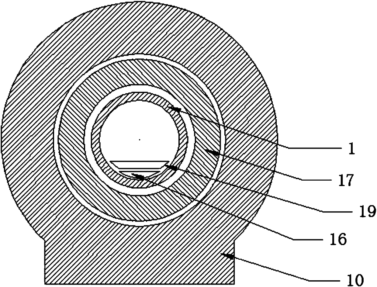
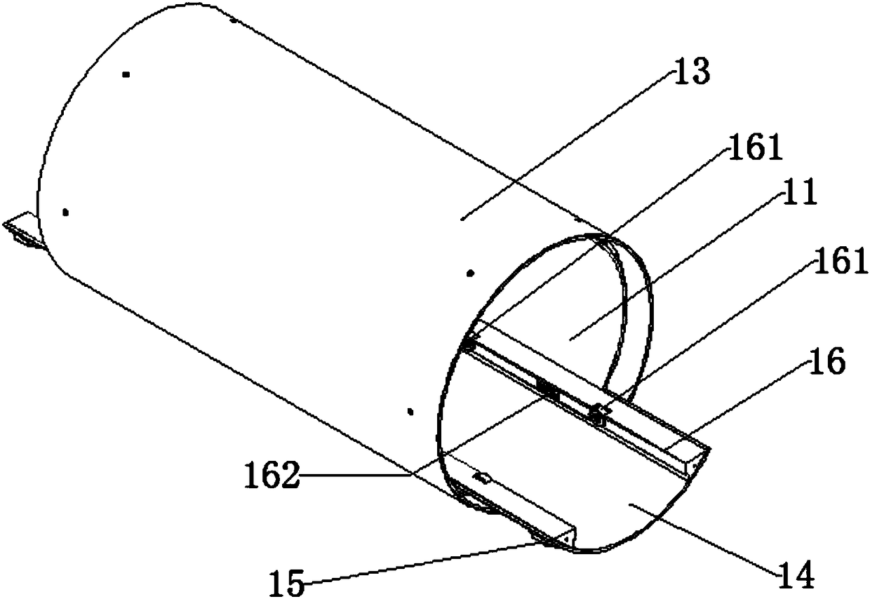
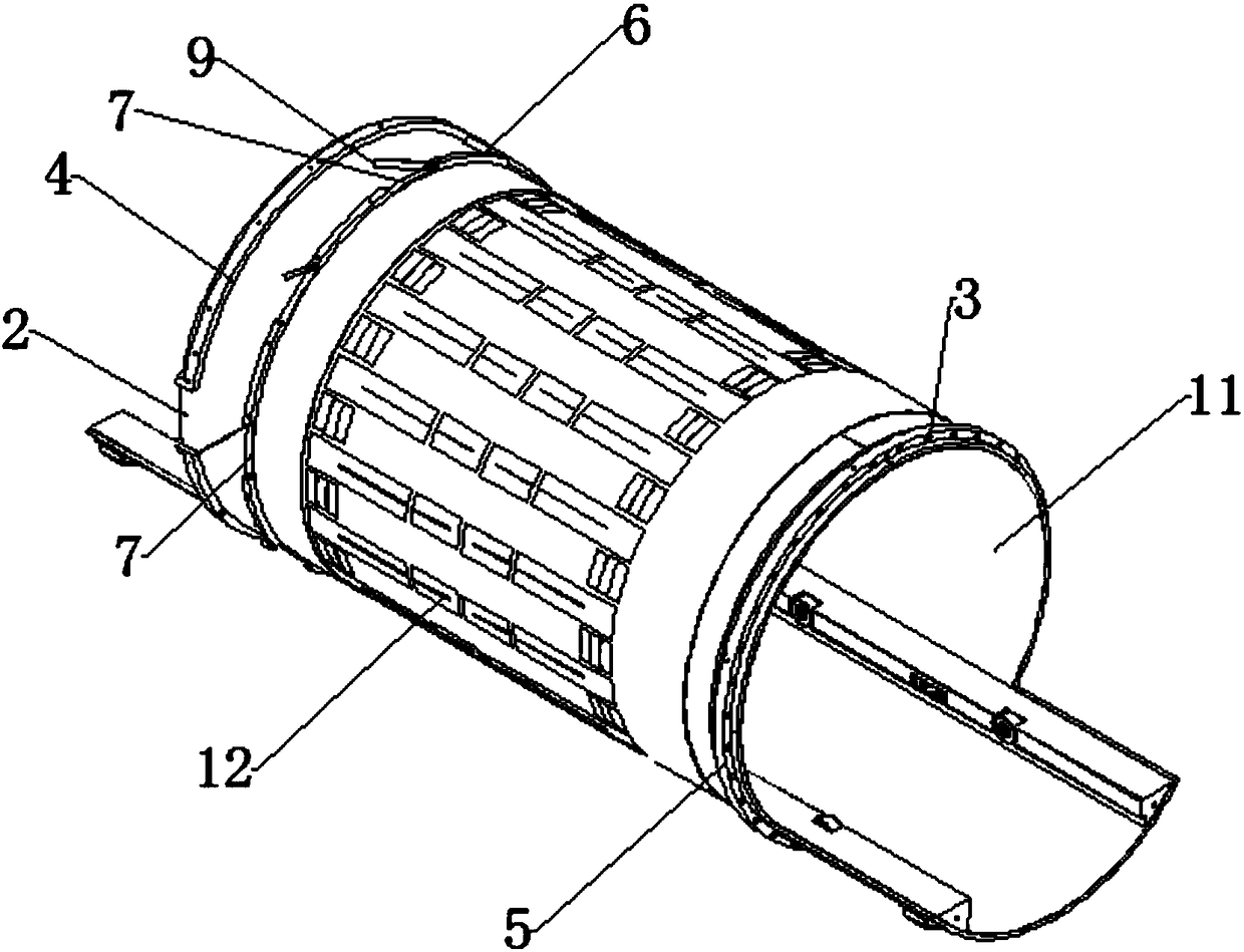
[0034] like figure 2 , 3 As shown, the MRI body coil structural assembly disclosed in the present invention includes a body coil 1 and an outer cylinder 13, the body coil 1 includes an inner cylinder 11 and an electronic component 12, the electronic component 12 is arranged on the outer wall of the inner cylinder 11, and the outer cylinder 13 is set Outside the inner cylinder 11 , a heat dissipation passage is formed between the inner wall of the outer cylinder 13 and the outer wall of the inner cylinder 11 , the air inlet 2 of the heat dissipation passage is located at one end of the body coil 1 , and the air outlet 3 of the heat dissipation passage is located at the other end of the body coil 1 . During specific use, air is sent to the air inlet 2 through the air supply pipe, and a fan is arranged at the air inlet of the air supply pipe, and the outlet of the air supply pipe is connected to the air inlet 2. The air flows quickly in the heat dissipation channel, quickly tak...

Embodiment 2

[0042] The difference between this embodiment and Embodiment 1 is that the outer cylinder 13 is a soundproof cylinder, such as Figure 7 As shown, the outer cylinder 13 includes a sound-insulating outer cylinder 131 , a sound-insulating inner cylinder 132 and a sound-insulating and sound-absorbing material 133 , and the sound-insulating and sound-absorbing material 133 is filled between the sound-insulating outer cylinder 131 and the sound-insulating inner cylinder 132 . The sound insulation tube can effectively reduce the noise level inside the inner tube 11 and reduce the patient's discomfort.

Embodiment 3

[0044] The difference between this embodiment and Embodiment 1 or 2 is: this embodiment also includes an air supply device (not shown in the figure), the air supply device includes a fan and an air supply pipe, and a fan is arranged at the air inlet of the air supply pipe, The tuyere 2 is connected with the air supply pipe.


PUM


Abstract

The invention relates to a MRI body coil structural assembly. The MRI body coil structural assembly comprises a body coil and an outer cylinder, the body coil comprises an inner cylinder and electronic components, the electronic components are arranged on an outer sidewall of the inner cylinder, the outer cylinder is arranged outside the inner cylinder in a sleeved manner, a heat radiation channelis formed between an inner wall of the outer cylinder and an outer wall of the inner cylinder, an air inlet of the heat radiation channel is located at one end of the body coil, an air outlet of theheat radiation channel is located at the other end of the body coil, and the outer cylinder is a sound insulation cylinder. The MRI body coil structural assembly is provided with a ventilation heat radiation structure and an air diverting structure so that the heat generated by the electronic components can be uniformly taken away with high efficiency, the lifetime of the components is prolonged,and the discomfort of patients is reduced; the sound insulation cylinder is additionally provided so that the noise generated by a gradient coil can be effectively reduced, and a more comfortable environment is provided for staff and tested patients; the body coil is arranged on a magnet so that the vibration of the body coil can be reduced, and the imaging quality is improved; and a sickbed guiderail is integrated on the body coil so that the cost is reduced, the installation is convenient, and the problem of difficult removal of small sucked metal materials is solved.

Description

technical field [0001] The invention relates to the technical field of nuclear magnetic resonance equipment, in particular to an MRI body coil structural assembly. Background technique [0002] like figure 1 As shown, in the magnetic resonance system, the gradient coil (serial number 17) is mounted on the magnet (serial number 10) through a fastening device, and the body coil (serial number 1) is located in the gradient coil. (No. 19) will carry the patient through the bed board guide rail (No. 16) and slide to the scanning area in the body coil. When performing long-term high-power scanning, the electronic components on the outer wall of the body coil generate a lot of heat. If the heat is not dissipated in time, on the one hand, the life of the electronic components will be affected, and on the other hand, the heat will be transferred to the inner wall of the body coil. There is a burning sensation. In addition, because the gradient coil is subjected to electromagnetic ...

Claims


Application Information

Patent Timeline
Patent Type & Authority Applications(China)
IPC IPC(8): G01R33/34A61B5/055
CPCA61B5/055G01R33/34
Inventor 陈宏刘春宝赵勇
Owner ALLTECH MEDICAL SYST
Why Eureka
Try Eureka