

Electroplating tank
A technology for electroplating tanks and tank bodies, applied in the direction of plating tanks, etc., can solve the problem that the crystallization of the plating solution is easy to damage the sealing effect, and achieve the effect of preventing crystallization and improving sealing
- Summary
- Abstract
- Description
- Claims
- Application Information
AI Technical Summary
Problems solved by technology
Method used
Image

Examples
Embodiment 1
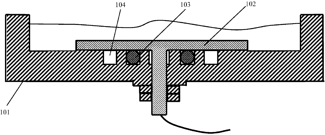
[0020] Such as figure 1 The illustrated electroplating tank includes a tank body 101 and an anode plate 102 . The anode plate 102 is T-shaped, and the free end in the vertical direction is threaded. There is a through hole at the bottom of the tank body 101. The anode plate 102 is arranged on the tank body 101 through the through hole and the nut, so as to better fix the anode The plate 102 is usually secured using double nuts. In order to ensure the sealing effect of the electroplating tank, an inner sealing ring 103 is provided between the tank body 101 and the anode plate 102, and the inner sealing ring 103 is usually an O-ring. There is a ring of deionized water tank 104 outside the inner sealing ring 103, and the deionized water tank 104 is arranged on the tank body 101, and the deionized water tank 104 and the inner sealing ring 103 form a concentric ring. The deionized water tank 104 is suitable for containing deionized water. The deionized water can effectively dilut...
Embodiment 2
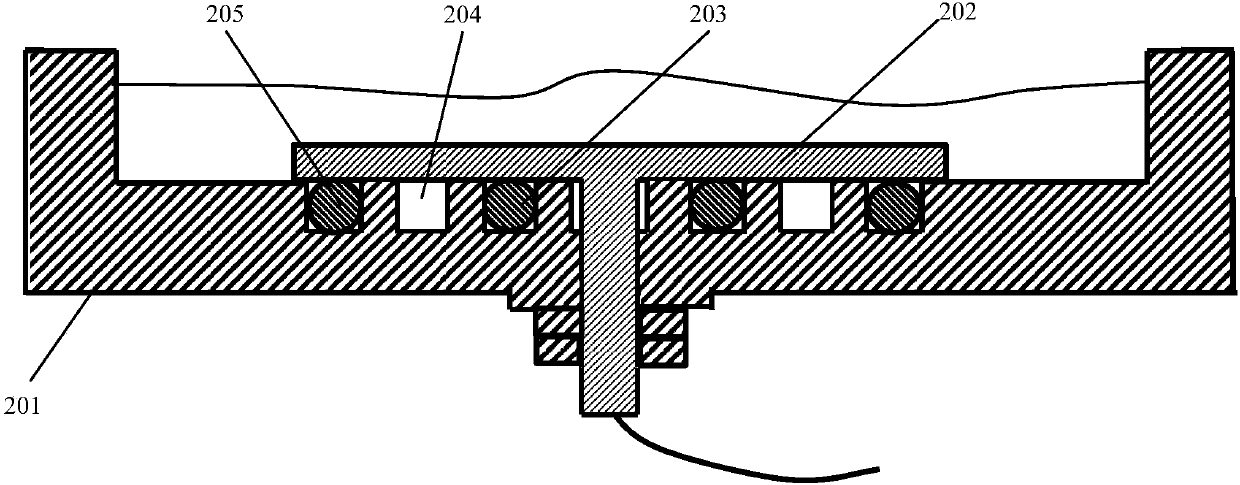
[0022] figure 2 Shown is another embodiment of an electroplating tank, including a tank body 201 and an anode plate 202 . The anode plate 202 is T-shaped, and the free end in the vertical direction is threaded. There is a through hole at the bottom of the tank body 201. The anode plate 202 is fixed on the tank body 201 through the through hole and the nut. In order to better fix the anode The plate 202 is usually secured using double nuts. In order to ensure the sealing effect of the electroplating tank, a double sealing ring sealing method is adopted, that is, an inner sealing ring 203 and an outer sealing ring 205 are arranged between the tank body 201 and the anode plate 202, and the two sealing rings can be concentric rings, and the inner sealing ring Ring 203 and outer seal ring 205 are typically O-ring seals. There is an annular U-shaped groove on the contact surface between the tank body 201 and the two sealing rings, and the sealing ring is pressed into the U-shaped...
Embodiment 3
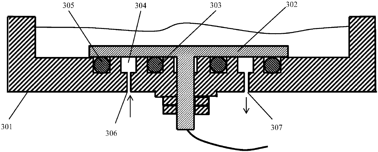
[0025] image 3 Shown is yet another specific embodiment of the electroplating tank, including a tank body 301 and an anode plate 302 . The anode plate 302 is T-shaped, and the free end in the vertical direction is threaded. There is a through hole at the bottom of the tank body 301. The anode plate 302 is fixed on the tank body 301 through the through hole and the nut. In order to better fix the anode Plate 302, usually secured with double nuts. In order to ensure the sealing effect of the electroplating tank, a double sealing ring sealing method is adopted, that is, an inner sealing ring 303 and an outer sealing ring 305 are arranged between the tank body 301 and the anode plate 302. The two sealing rings can be concentric rings, and the inner sealing ring Ring 303 and outer seal ring 305 are typically O-ring seals. There is an annular U-shaped groove on the contact surface between the tank body 301 and the two sealing rings, and the sealing ring is pressed into the U-shap...
PUM
 Abstract
Description
Claims
Application Information