
Light-emitting diode display panel

A technology of light-emitting diodes and display panels, applied in optics, optical components, instruments, etc., can solve problems such as reduced ambient light reflectivity and impact on display quality, and achieve the effect of improving display quality and preventing impact

Active Publication Date: 2015-01-28
BOE TECH GRP CO LTD +1
View PDF4 Cites 16 Cited by
  • Summary
  • Abstract
  • Description
  • Claims
  • Application Information

AI Technical Summary

Problems solved by technology

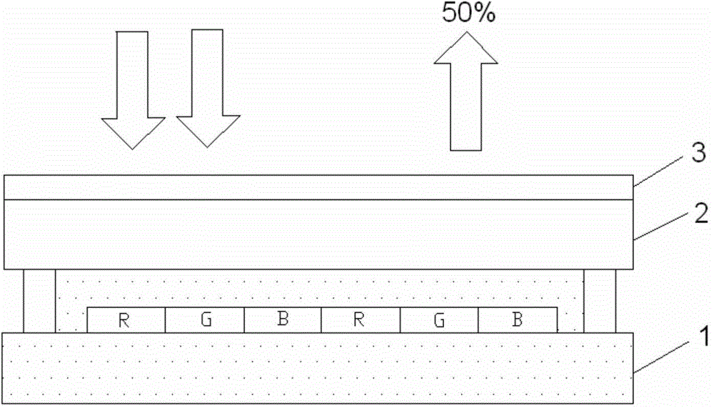
Although the reflectivity of the light-emitting diode display panel to ambient light is reduced after the polarizer 3 is installed, the reflected 50% of the ambient light will still affect the display quality.

Method used


Image

  • Light-emitting diode display panel
  • Light-emitting diode display panel
  • Light-emitting diode display panel

Examples


Embodiment Construction

[0028] Specific embodiments of the present invention will be described in detail below in conjunction with the accompanying drawings. It should be understood that the specific embodiments described here are only used to illustrate and explain the present invention, and are not intended to limit the present invention.

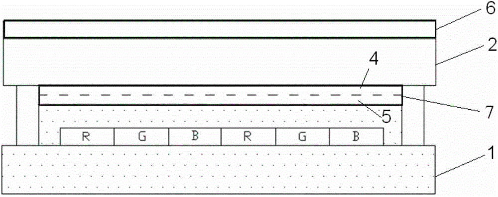
[0029] The present invention provides a light emitting diode display panel, comprising a first substrate for displaying, a second substrate for encapsulating the first substrate, and a polarizing layer, and the light emitting diode display panel further includes a λ / 4 phase retardation film The arrangement of the polarizing layer and the λ / 4 phase retardation film makes the incident ambient light pass through the polarizing layer and the λ / 4 phase retardation film in sequence and then reach the first substrate.

[0030] The light emitting diode display panel here may be an organic light emitting diode (OLED, Organic Light Emitting Diode) display panel, or an act...


PUM


Abstract

The invention discloses a light-emitting diode display panel, and relates to the technical field of display. The light-emitting diode display panel comprises a first substrate used for displaying, a second substrate used for packaging the first substrate, a polarizing layer, and a lambda / 4 phase retardation film. The polarizing layer and the lambda / 4 phase retardation film are arranged to enable incident ambient light to reach the first substrate sequentially through the polarizing layer and the lambda / 4 phase retardation film. By arranging the polarizing layer and the lambda / 4 phase retardation film in the light-emitting diode display panel at the same time, the influence of the reflection of ambient light to the display screen is effectively prevented, and the display quality is enhanced.

Description

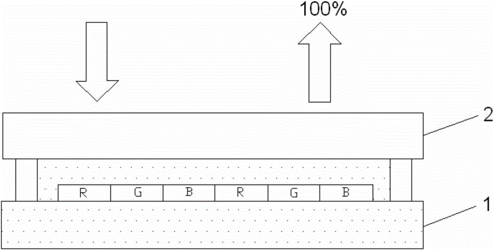
technical field [0001] The invention relates to the field of display technology, in particular to a light emitting diode display panel. Background technique [0002] Light-emitting diode display panels are the development trend of future display products, especially organic light-emitting diode display panels, which have a series of advantages such as wide viewing angle, fast response speed, high brightness, high contrast, bright colors, light weight, thin thickness, and low power consumption. . [0003] figure 1 It is a structural schematic diagram of an existing light-emitting diode display panel, and the light-emitting diode display panel includes a first substrate 1 and a second substrate 2 . The first substrate 1 includes an anode, a cathode, a light emitting layer, a color filter layer, a hole injection layer, a hole transport layer, an electron transport layer, a protective film and other inherent structures of the LED display panel. figure 1 The light-emitting dio...

Claims


Application Information

Patent Timeline
IPC IPC(8): H01L27/32
CPCG02B1/11G02B27/28G02B5/3016G02B5/3033G02B5/3058H10K59/8791H10K50/868H10K50/86H10K71/00
Inventor 杨发禄张俊瑞
Owner BOE TECH GRP CO LTD
Learn More