Optical module

An optical module and laser technology, applied in the field of optical communication, can solve the problems of high fiber cost, inability to use general-purpose devices, and high device development costs, and achieve the effects of improving reliability, reducing device costs, and reducing manufacturing costs.

Active Publication Date: 2015-01-28
INNOLIGHT TECHNOLOGY (SUZHOU) LTD
View PDF13 Cites 2 Cited by
  • Summary
  • Abstract
  • Description
  • Claims
  • Application Information

AI Technical Summary

Problems solved by technology

The disadvantage of this solution is: Mux / DeMux packaging is mostly realized by Free space or PLC
The disadvantage of this solution is: the cost of optical fiber is too high
The disadvantage of this solution is that it needs to use a laser with a special band, but cannot use a general-purpose device, and the device development cost is high

Method used


Image

  • Optical module
  • Optical module
  • Optical module

Examples


Embodiment Construction

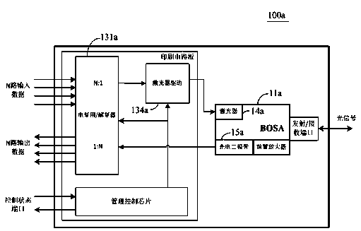
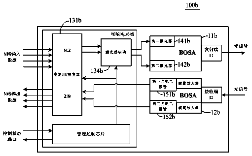
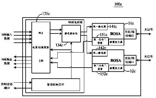
[0050]The application will be described in detail below in conjunction with specific implementations shown in the accompanying drawings. However, these implementations do not limit the present application, and any structural, method, or functional changes made by those skilled in the art based on these implementations are included in the protection scope of the present application.

[0051] It should be understood that although the terms first, second, etc. may be used herein to describe various elements or structures, these described objects should not be limited by these terms. These terms are only used to distinguish these described objects from one another. For example, a first laser may be called a second laser, and similarly a second laser may also be called a first laser, without departing from the scope of protection of the present application.

[0052] In different implementations / embodiments, the same symbols or signs may be used, but this does not represent a struc...


PUM


Abstract

The invention discloses an optical module which comprises a first laser, a second laser, a first photodiode, a second photodiode and a 2:N electrical multiplexing / de-multiplexing device. The 2:N electrical multiplexing / de-multiplexing device is used for converting N paths of input data into two paths of multi-frequency sending data to drive the first laser and the second laser respectively, and converting the two paths of multi-frequency receiving data from the first photodiode and the second photodiode into N paths of output data. According to the technical scheme, by the adoption of the electrical multiplexing / de-multiplexing device, data electrical signals are multiplexed, the number of the optical devices, needing to be driven, such as the lasers, the photodiodes, laser drivers and TIA pre-amplifiers is reduced correspondingly, the cost of the devices is reduced, the encapsulation of the optical module can be achieved by adopting a BOSA structure, the manufacturing cost is lowered, and the reliability of products is improved.

Description

technical field [0001] The invention belongs to the technical field of optical communication, and in particular relates to an optical module. Background technique [0002] Optical communication technology is playing an increasingly important role in modern society. In practical applications, reliability and low cost are important factors that affect the competitiveness of optical communication device products. The existing four-channel SFP interface (Quad Small Form-factor Pluggable, QSFP) solutions mainly include the following: [0003] 1) QSFP+ 40G LR4: Four-wavelength CWDM 10G DFB lasers are used, 4-channel Mux / deMux is used to realize coupling and decoupling, and a single-mode optical fiber is used for signal transmission, with a transmission distance of 10km. The disadvantage of this solution is: Mux / DeMux packaging is mostly realized by Free space or PLC. However, the PLC structure device has high cost and large insertion loss; the Free space solution has a complex s...

Claims


Application Information

Patent Timeline
Patent Type & Authority Applications(China)
IPC IPC(8): H04B10/40
Inventor 王祥忠孙雨舟王克武
Owner INNOLIGHT TECHNOLOGY (SUZHOU) LTD
Why Eureka
Try Eureka