
Digital micromirror array coding flash three-dimensional imaging method and device

A digital micromirror array and three-dimensional imaging technology, which is applied in the field of three-dimensional imaging, can solve problems such as the failure of three-dimensional imaging errors of moving targets, and achieve the effect of avoiding low integration

Active Publication Date: 2015-01-28
INST OF SEMICONDUCTORS - CHINESE ACAD OF SCI
View PDF8 Cites 19 Cited by
  • Summary
  • Abstract
  • Description
  • Claims
  • Application Information

AI Technical Summary

Problems solved by technology

[0006] Aiming at the deficiencies in the above-mentioned prior art, the main purpose of the present invention is to propose a digital micromirror array coded flash three-dimensional imaging method and its device, so as to solve the problem of inter-frame delay of the image sensor in range-gated super-resolution three-dimensional imaging. In order to achieve the real-time range-gated super-resolution three-dimensional imaging

Method used


Image

  • Digital micromirror array coding flash three-dimensional imaging method and device
  • Digital micromirror array coding flash three-dimensional imaging method and device
  • Digital micromirror array coding flash three-dimensional imaging method and device

Examples


Embodiment Construction

[0037] In order to make the object, technical solution and advantages of the present invention clearer, the present invention will be further described in detail below in conjunction with specific embodiments and with reference to the accompanying drawings.

[0038] Descriptions of structural embodiments and methods of the invention are disclosed herein. It is to be understood that the intention is not to limit the invention to the particular disclosed embodiments, but that the invention can be practiced using other features, elements, methods and embodiments. Similar elements in different embodiments are generally labeled with similar numbers.

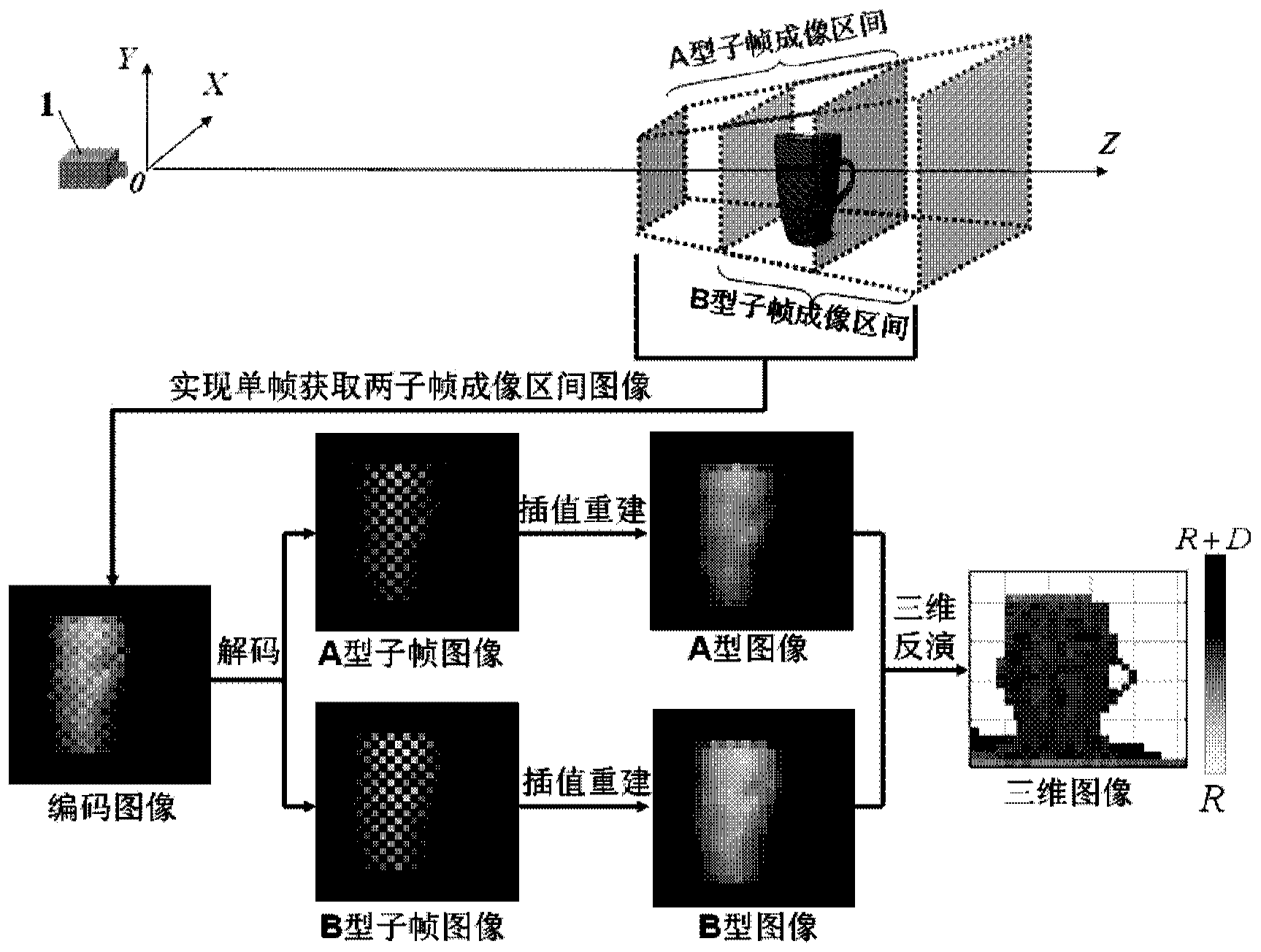
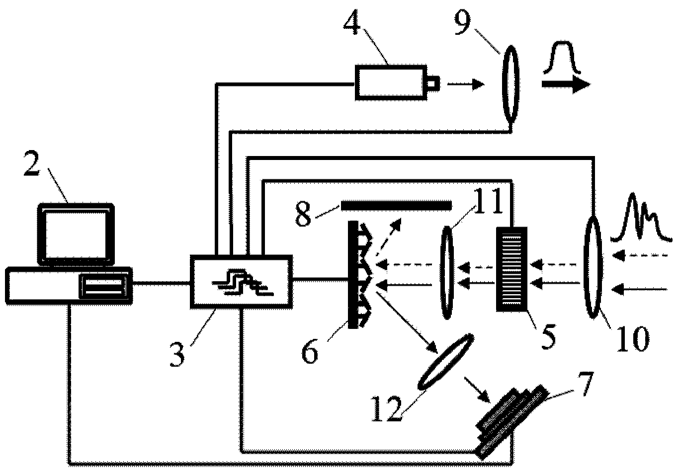
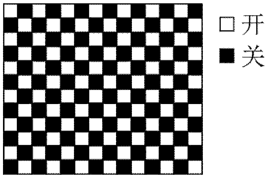
[0039] figure 1 It is a schematic diagram of the working principle of the digital micromirror array coded flash three-dimensional imaging method of the present invention, and FIG. 2 is a structural schematic diagram of the digital micromirror array coded flash three-dimensional imaging device of the present invention. Such as figur...


PUM


Abstract

The invention discloses a digital micromirror array coding flush three-dimensional imaging method and device. The device comprises a computer, a center controller, a pulse laser, a lighting lens, an imaging lens, a gating shutter, a shaping lens, a digital micromirror array, a coupling lens, an image sensor and a light absorbing board, wherein the center controller is used for generating a coding flash work timing sequence; the pulse laser is used for generating laser pulses; the lighting lens is used for lighting an imaging target in a field of view; the imaging lens is used for collecting a target echo signal formed by the imaging target subjected to irradiation of the laser pulses; the gating shutter is used for collecting and amplifying the target echo signal; the shaping lens is used for performing optical shaping on the target echo signal amplified by the gating shutter and coupling the target echo signal to the digital micromirror array which reflects a part of the target echo signal to the coupling lens and the rest of the target echo signal to the light absorbing board; the coupling lens is used for shaping the target echo signal reflected by the digital micromirror array and coupling the target echo signal to the image sensor which carries out imaging according to the received target echo signal; the light absorbing board is used for absorbing the target echo signal irradiated the light absorbing board.

Description

technical field [0001] The invention belongs to the technical field of three-dimensional imaging, and in particular relates to a digital micromirror array coding flash three-dimensional imaging method and device. Background technique [0002] Long-distance and fast three-dimensional imaging has great significance and broad application prospects in the fields of space rendezvous and docking, obstacle avoidance navigation, missile guidance, and moving target detection and recognition in complex environments. [0003] At present, the typical representative technology of long-distance and fast three-dimensional imaging is three-dimensional flash laser imaging radar (Flash Lidar). Integrated circuit, when working, after the pulse laser emits a laser pulse, each APD unit can use the readout integrated circuit to record the intensity and time delay information of the echo signal formed after the laser pulse is reflected by the target, and then use the time delay information to refl...

Claims


Application Information

Patent Timeline
Patent Type & Authority Applications(China)
IPC IPC(8): H04N5/225G06T17/00
Inventor 王新伟李友福周燕
Owner INST OF SEMICONDUCTORS - CHINESE ACAD OF SCI
Learn More