Modular removable thermal insulation

A modular, removable technology for the protection of pipes through thermal insulation, heat exchange equipment, climate sustainability, etc., which can solve problems such as difficult access to frame members, complex installation, and inability to ensure surface isothermal properties.

Inactive Publication Date: 2015-01-28
鲍里斯·弗拉基米劳维奇·柯拉基诺夫
View PDF8 Cites 5 Cited by
  • Summary
  • Abstract
  • Description
  • Claims
  • Application Information

AI Technical Summary

Problems solved by technology

[0003] Disadvantages of the above structure include: during operation of the device for adjusting the belt fastening force, it will be difficult to access (accessibility) frame member (frame member); , the installation of the TIM is very complex; where the through-hole is lined with a metal tube and used for threaded fixings
[0005] However, the field of application of this prototype is limited due to the fact that the TIM is fixed to an element soldered to the device to be insulated
In other words, this prototype cannot be applied to thermal insulation of pow...

Method used


Image

  • Modular removable thermal insulation
  • Modular removable thermal insulation
  • Modular removable thermal insulation

Examples


Embodiment Construction

[0050] best practice

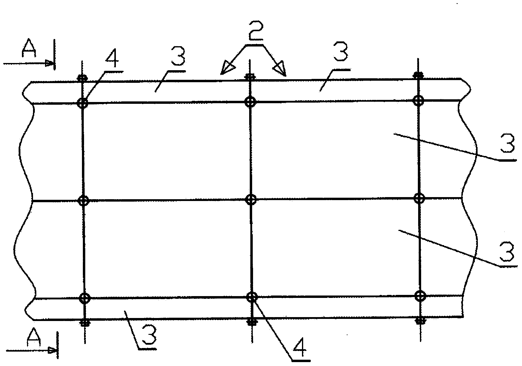
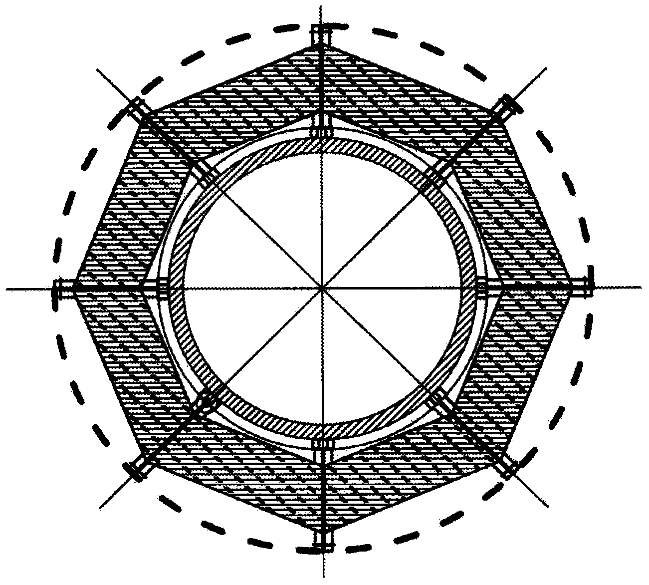
[0051] The modular removable thermal insulation structure according to the invention comprises circular segments 2 distributed longitudinally in series on the outer surface of the equipment to be insulated, for example the outer surface of the pipe 1; and the circular segments 2 close to each other. Each circular segment consists of N identical thermal insulation modules (TIM) 3 . The thermal insulation modules 3 abut against each other; and the side walls of the TIM 3 of adjacent sections are arranged opposite to each other. Thus, each of the four corner posts between the side walls of each TIM 3 butts along a joint line 4; wherein this joint line 4 extends in a direction normal to the surface of the device to be insulated. On the one hand, between the side walls of the TIM 3 there is a corner fitting corresponding to each corner post, the corner fittings being located in the same segment and in the vicinity of the TIM 3 . On the other hand, there ar...


PUM


Abstract

The present invention relates generally to the thermal insulation technology, and more particularly to a thermal insulation for equipment at nuclear power plants (NPPs). The advantages of the present invention includes the widening of the field of application; the simplification of both installation and dismantling of the thermal insulation modules; an increase in the isothermality of an equipment to be thermally insulated; a uniform distribution of a temperature field within the thermal insulation volume along the length thereof; and the possibility of monitoring the state of the equipment body without need to remove the thermal insulation modules.

Description

technical field [0001] The present invention relates to thermal insulation technology, and more particularly, to a thermal insulation structure (thermal insulation) for nuclear power equipment (NNP). Background technique [0002] A modular removable insulation structure is known in the prior art, comprising a tie band type housing and an enclosure. Wherein, the strap-type housing has a threaded seat body and is positioned so that the fixed wire is located on the outer surface of the device to be insulated. The casing surrounds the above-mentioned equipment to be insulated, and includes an N-face outer surface and an N-face inner surface. The housing is composed of circular sections; wherein said circular sections are successively distributed longitudinally on the device to be insulated and abut against each other. Each circular segment consists of N identical thermal insulation modules (TIMs). The thermal insulation modules are butted against each other, and the respectiv...

Claims


Application Information

Patent Timeline
IPC IPC(8): F16L59/00F16L59/14
CPCG21C11/08Y02E30/40Y02E30/30F16L59/14
Inventor 鲍里斯·弗拉基米劳维奇·柯拉基诺夫
Owner 鲍里斯·弗拉基米劳维奇·柯拉基诺夫
Why Eureka
Try Eureka