Stitch needle-bending tool special for wheel speed sensor

A wheel speed sensor and looper technology, which is applied in the field of wheel speed sensor special pin looper tooling, can solve the problems of not meeting the requirements of mass production, high requirements for workers' operation, and difficulty in guaranteeing bending requirements, etc., so as to reduce the scrap rate of products , Guarantee personal safety and high processing precision

Active Publication Date: 2015-02-04
安徽南科电子控股集团有限公司
View PDF7 Cites 6 Cited by
  • Summary
  • Abstract
  • Description
  • Claims
  • Application Information

AI Technical Summary

Problems solved by technology

At present, the bending needle is mainly bent manually, which is not only time-consuming and laborious, and the bending requirements are difficult to guarantee, but also the efficiency is extremely low, which does not meet the needs of mass processing and production; there are also simple bending tools for the bending process, the tooling The bending needle is bent by pushing the bending parts manually, and the bending by human power has high requirements on the operation of the workers and is prone to fatigue; and if the bending tooling is not operated carefully, once the bending does not meet the requirements If the second bending is carried out, the product will easily be scrapped; moreover, since there are two different bending positions, two different bending processes and bending tools are required, and the production efficiency obviously cannot be improved.

Method used


Image

  • Stitch needle-bending tool special for wheel speed sensor
  • Stitch needle-bending tool special for wheel speed sensor
  • Stitch needle-bending tool special for wheel speed sensor

Examples


Embodiment 1

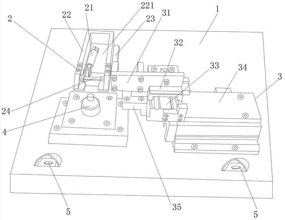
[0025] Example 1: Reference figure 1 . A special needle looper tooling for wheel speed sensor, including workbench 1, first looper assembly 2, second looper assembly 3, workpiece positioning head 4, first looper assembly 2, second looper assembly 3, and workpiece The positioning heads 4 are all arranged on the worktable 1, the rear side of the workpiece positioning head 4 is provided with a first looper assembly 1, and the right side thereof is provided with a second looper assembly 2. The workbench 1 is provided with two sets of touch switches 5 arranged at intervals, and the distance between the two touch switches 5 is at least 20 mm. In specific use, two hands of the worker are required to touch the touch switches 5 to start operation. The bending process is: positioning the sensor core 8 on the workpiece positioning head 4, then starting the first bending needle assembly 2 to bend the side needle 82 of the sensor inner core 8, and then starting the second bending needle ass...

Embodiment 2

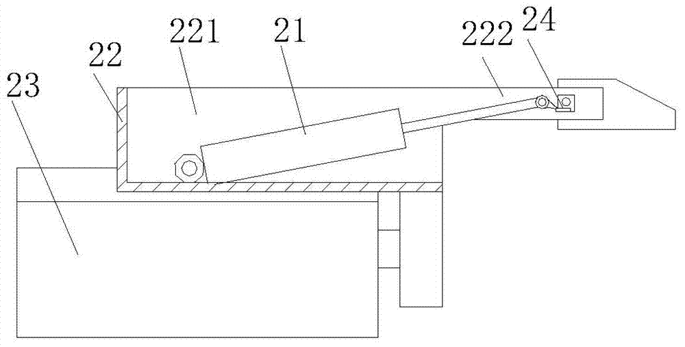
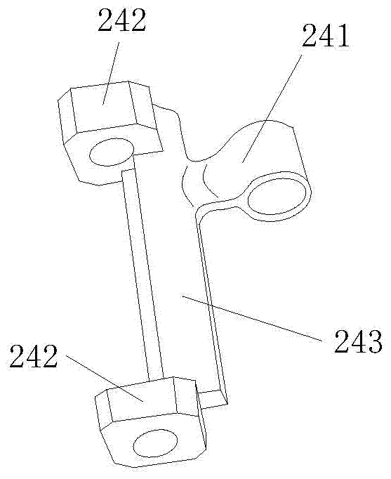
[0026] Example 2: Reference figure 2 , 3 . The first looper assembly 2 includes a bending arm cylinder 21, a side needle bending arm 24, a first sliding seat 22, and a first cylinder 23. The upper end of the first sliding seat 22 is provided with a mounting cavity 221, and the upper end of the first sliding seat 22 is two An extension arm 222 extends from the lateral workpiece positioning head in the 4-direction. Both ends of the side needle bending arm 24 are connected to the extension arms 222 on both sides of the upper end of the first sliding seat 22. The cylinder end of the bending arm cylinder 21 is connected to the first sliding seat 22. The side wall or bottom wall of the mounting cavity 221 of the seat 22 is hinged, the piston rod end is eccentrically hinged to the side needle bending arm 34, the cylinder end of the first cylinder 23 is fixed to the worktable 1, and the driving end is connected to the first sliding seat 22Connect. The side needle bending arm 21 is co...

Embodiment 3

[0027] Example 3: Reference Figure 4~7 . The second looper assembly 3 includes a thimble bending roller 36, a transverse drive cylinder 34, a longitudinal drive cylinder 33, a second sliding seat 32 and a thimble stopper 37. The second sliding seat 32 is connected to the driving end of the longitudinal drive cylinder 33, A connecting frame 31 is provided on its left side. The thimble bending roller 36 is located below the connecting frame 31, and its lateral and axial ends are rotatably connected to the connecting frame 31. The cylinder end of the longitudinal drive cylinder 33 and the lateral drive cylinder 34 The drive end of the horizontal drive cylinder 34 is connected to the workbench 1. The thimble stopper 37 is horizontally arranged on the front side of the thimble bending roller 36, and the thimble stopper 37 passes through the bracket 35 and the longitudinal drive cylinder 33 The cylinder end is connected. The thimble bending roller 36 includes a roller body 364 and...


PUM


Abstract

The invention relates to a stitch needle-bending tool special for a wheel speed sensor. The tool comprises a workbench, a first needle-bending component, a second needle-bending component and a workpiece positioning head, wherein the first needle-bending component, the second needle-bending component and the workpiece positioning head are arranged on the workbench; the first needle-bending component is arranged on the rear side of the workpiece positioning head; the second needle-bending component is arranged on the right side of the workpiece positioning head. Compared with the background technology, the tool has the advantages of simple structure, convenience in manufacturing, safety, reliability and high working efficiency; a sensor inner core is positioned on the workpiece positioning head, and a bending process is sequentially performed on two plugging needles extending out of the sensor inner core; the needle-bending components, such as a side needle bending arm, a top needle bending roller and a top needle baffle sheet are ingenious in manufacturing, and after the needle bending process is finished, a workpiece and the bent inserting needles are not scratched and damaged; the tool is suitable for batch processing and high in processing precision, and the product rejection rate is effectively reduced; a double-touch switch is adopted, and the needle-bending tool can be started by touch by the two hands of a worker, so that the two hands of the worker are enabled to depart from the tool, and the personal safety of the worker is guaranteed.

Description

Technical field [0001] The invention relates to an auxiliary processing tool, in particular to a special needle bent needle tool for a wheel speed sensor. Background technique [0002] A wheel speed sensor in the prior art, a passive wheel speed sensor, includes a housing and a sensor core. The sensor core is located in the housing, and the bottom of the sensor core is connected to the bottom of the housing. The sensor core includes a coil , Pin and skeleton, the axial side of the skeleton is provided with a coil on the radial outer side, two pins are encapsulated on the side wall on the other side of the skeleton axis, and the two ends of the pin are separated from the radial side wall of the skeleton and The axial side wall protrudes out. The coils and pins on the inner core and the skeleton are all injection-molded and packaged in the mold as a whole. In order to facilitate packaging and demolding after packaging, the pins respectively extend from the radial and top of the pa...

Claims


Application Information

Patent Timeline
Patent Type & Authority Applications(China)
IPC IPC(8): B21F1/00
CPCB21F1/00
Inventor 万国兴安来锋吴强
Owner 安徽南科电子控股集团有限公司
Why Eureka
Try Eureka